Hello!
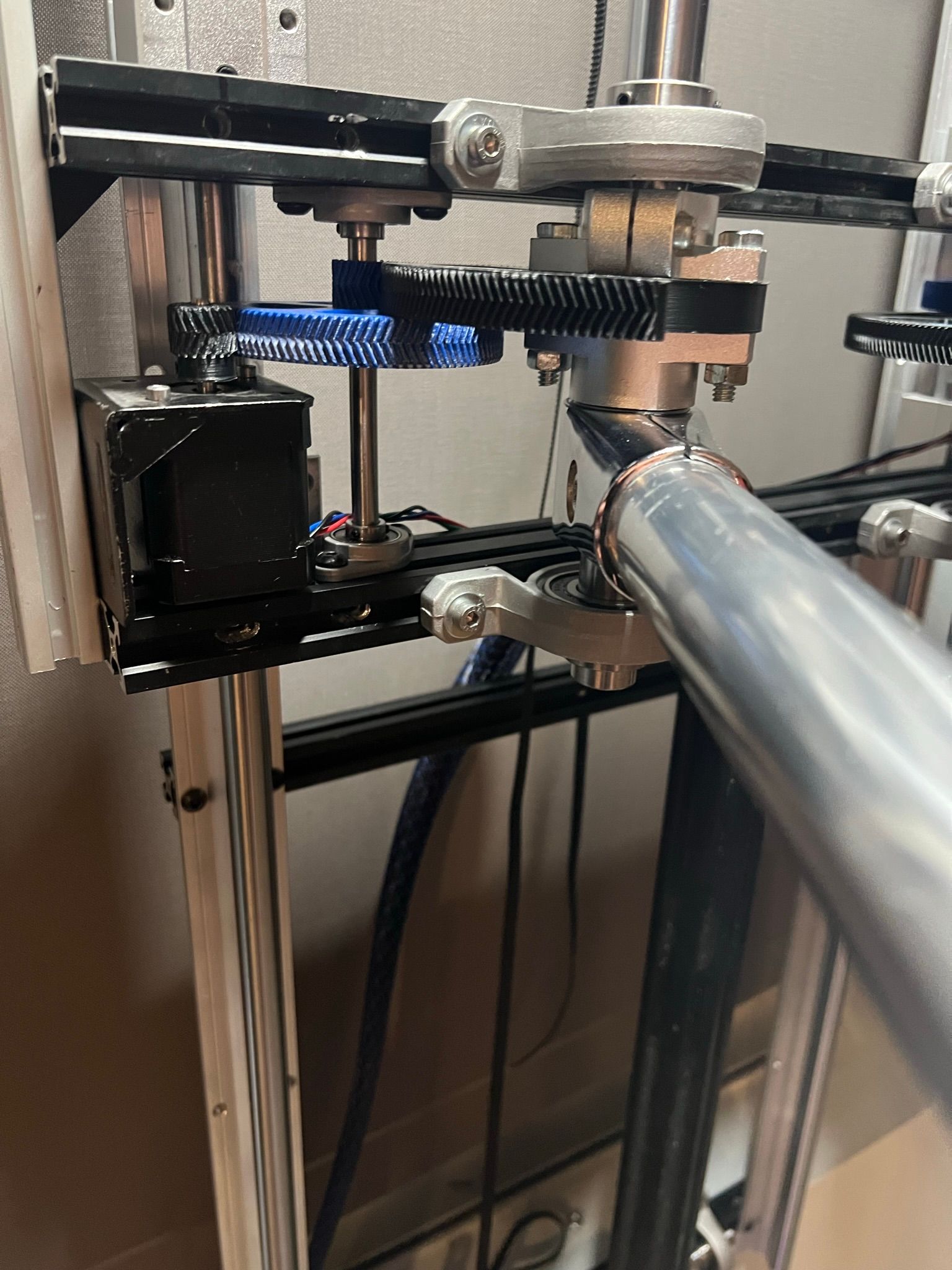
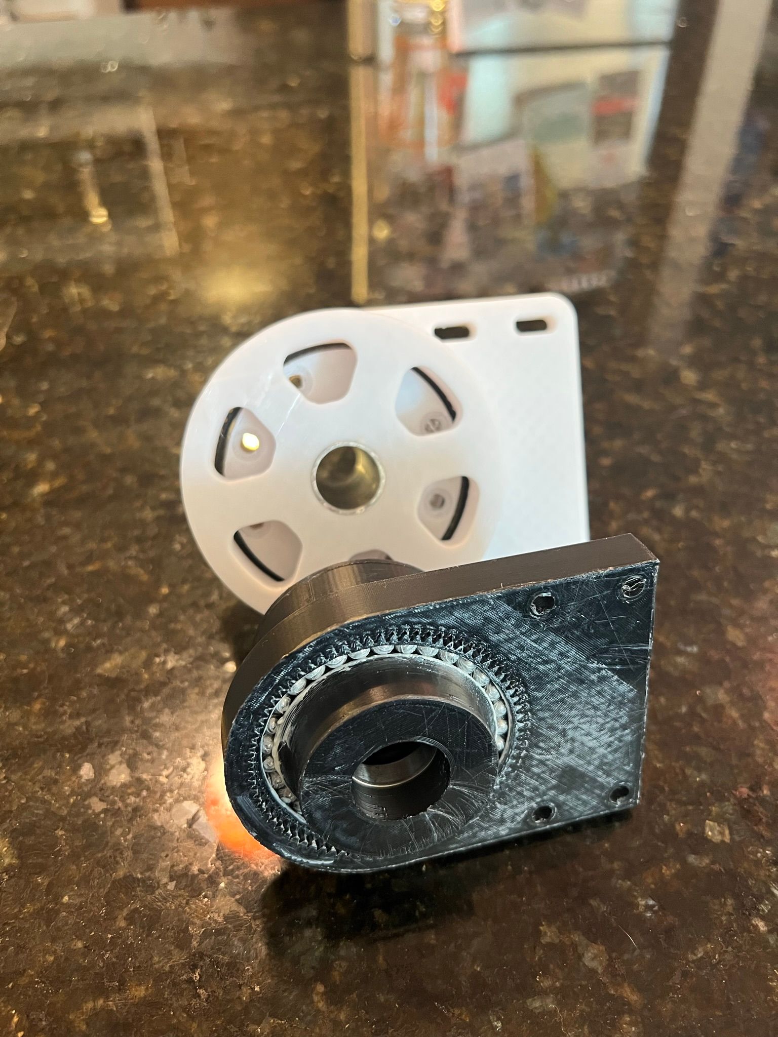
More changes and another update. I played around with a few more harmonic drive designs, and found they all had more backlash at the end effector than what I wanted. I had better luck with gear drives, and I also have found an appreciation for the back-drivability. So I scrapped the old design, developed a 45:1 gear drive design and rebuilt it one more time. I now think I have something workable at this point!
https://youtube.com/shorts/Yw_aW_2YJ5A
As you can see in the video, the system runs very smooth.
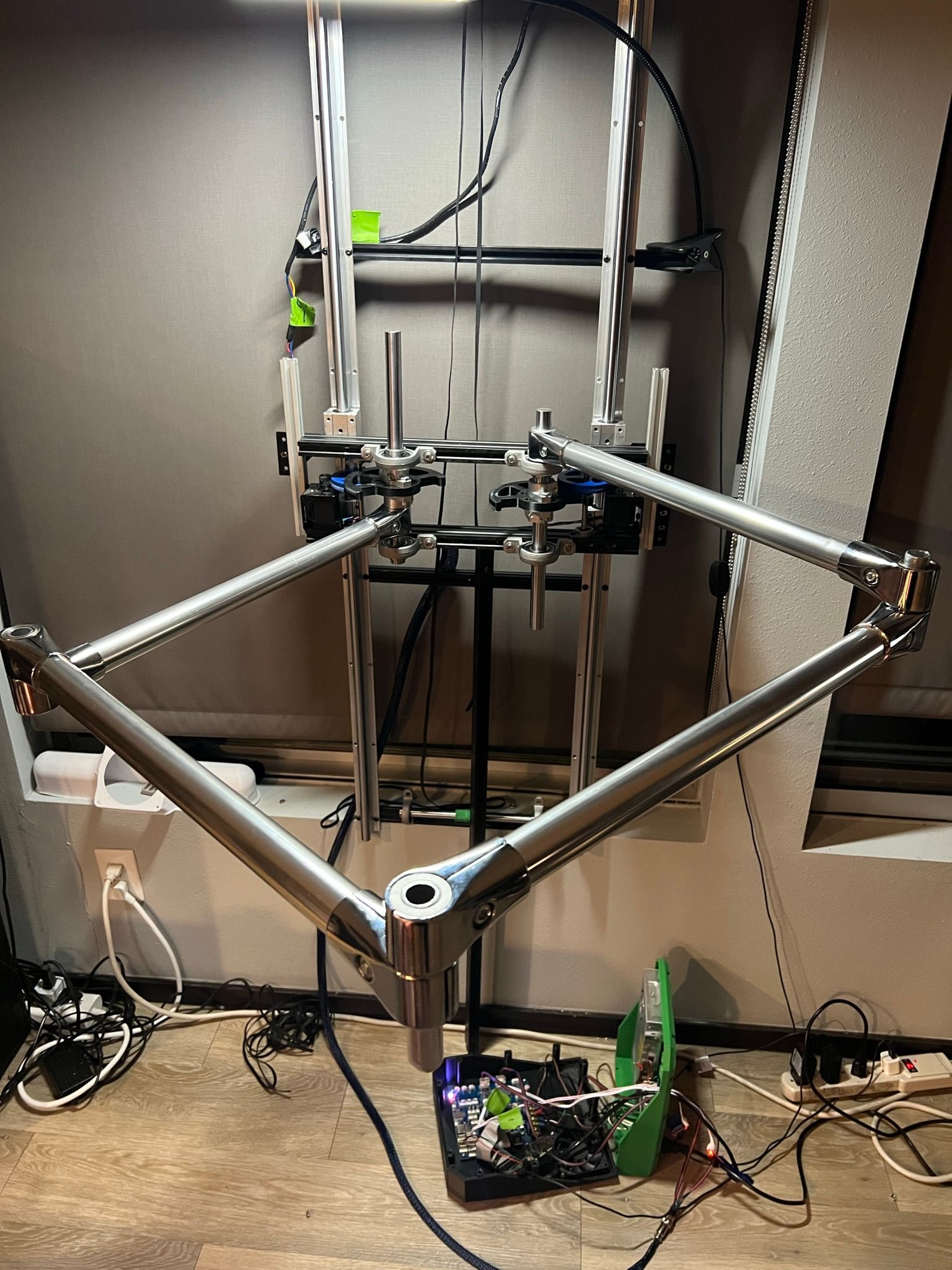
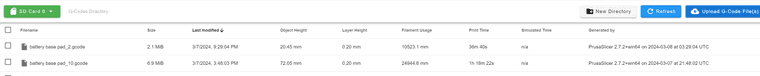
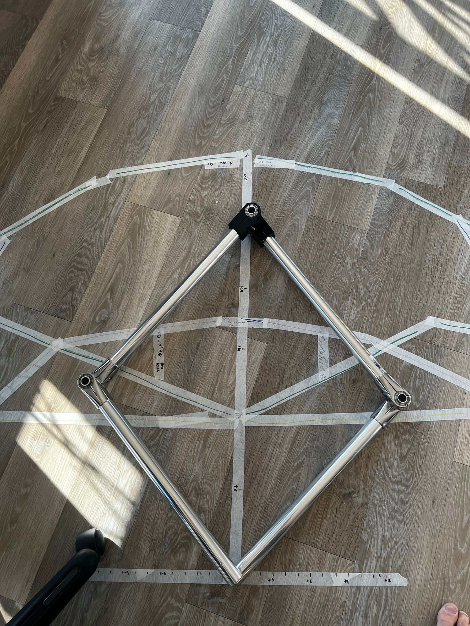
this is still running with just manual move codes, but now that I've got an XY motion system I'm going to start rebuilding the electronics to start working on calibration! List of things to knock out:
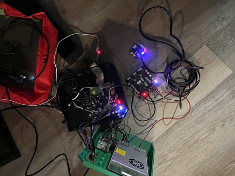
- Get endstops and other electrical bits cabled and installed
- Calibrate XY motion system
- Finish Z axis
- install extruder system and get a toolboard working
- get the build plate setup
- print something!


")
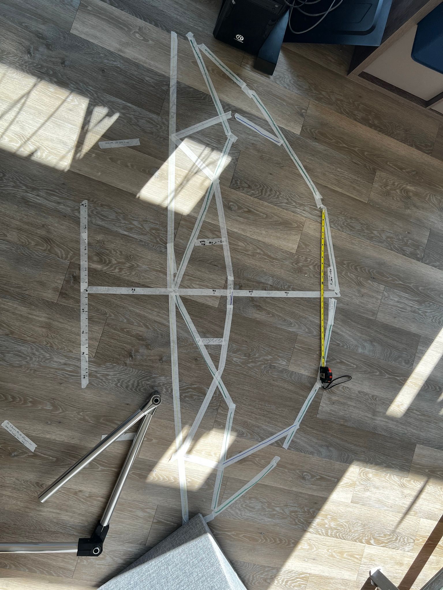
") the Z-axis definitely needs to be redone at some point. I reused an old v-rail setup I had on a leadscrew printer that I built a long time ago. The point of this system is to be able to print 30" or so parts for fiber glass molds, furniture, and just big parts in general out of mostly PETG and PLA, nothing crazy on the materials front, yet...
the Z-axis definitely needs to be redone at some point. I reused an old v-rail setup I had on a leadscrew printer that I built a long time ago. The point of this system is to be able to print 30" or so parts for fiber glass molds, furniture, and just big parts in general out of mostly PETG and PLA, nothing crazy on the materials front, yet...