Vertical Banding Problem and Stepper Waveforms
-
I've been troubleshooting a vertical banding artifact on my large format machine for some time now.

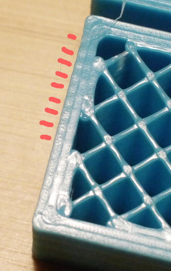
After two redesigns of the X-Y gantry, I'm somewhat convinced that the banding is from the actual movement of the stepper motors. It's not vibration from flexing of the linear shafts, it's not chatter in the linear bearings, and it's not matched to the belt tooth pitch. It gets worse if I decrease the stepper current, but not better than in the above image even with 1.4A. The band pitch increases when printing at higher speeds and becomes more dense with lower speed, so the deviation may be constant in time. Finally, the bands are due to the extruder stuttering along the direction of travel. That is, a single trace shows variation in thickness, not wobble. The pinkish marks attempt to point this out here:
So my current theory is that there's a periodic variation in the speed of the motors.
With insights from a friend, I got to wondering about noise in the drive signal for the motors, and I indeed found a significant (20v) periodic voltage swing in the stepper drive signal. That was eliminated completely when I found a problem with the ground on my 24v supply, and I was thrilled thinking I was home free, but alas it had no effect on the banding (!).
Wit's end is approaching.
In addition to general thoughts/insights, I wonder if anyone who knows exactly how clean the stepper drive signal should be can tell me if the scope plots below look reasonable. I'm going to probe my other printer (Makergear M2) for comparison tomorrow.
The below images were taken when probing one of the pins on the Y output on the Duet board directly. It's a differential measurement on two of the pins but the scope is just showing 1 channel for clarity.
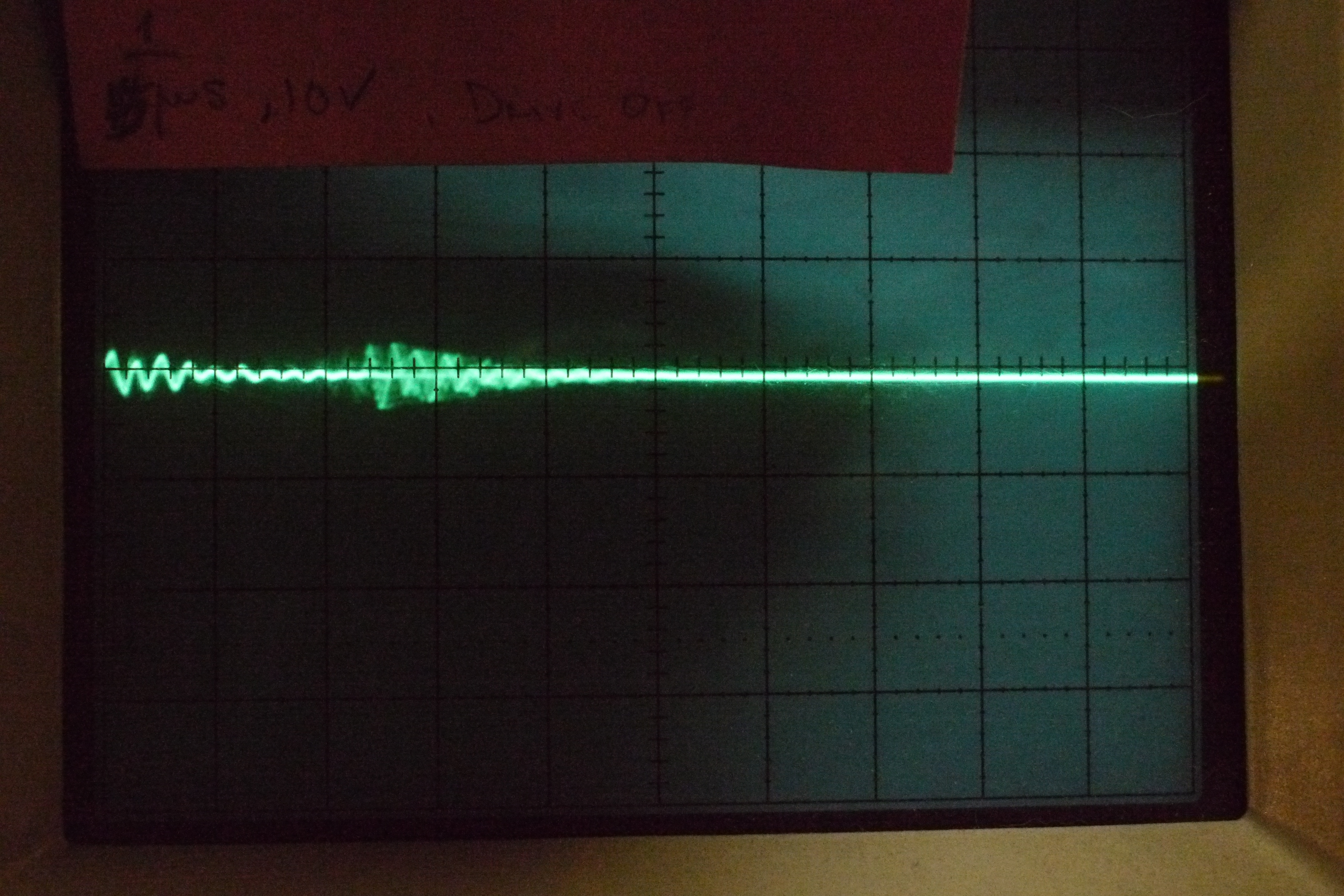
This is with the board on but the drive OFF. 1us and 10v per division. Notice the ~5v p-p ripple, and again 25us following. The 5v ripple seems like alot, and the second ripple (from the left) has the look of a reflection/echo, but I don't know:
This to me is the really strange one. Again 1us and 10v per division, but this time the drive is ON and the motor is not moving. Shouldn't that square wave be off completely (0% pwm) with the motor not moving?
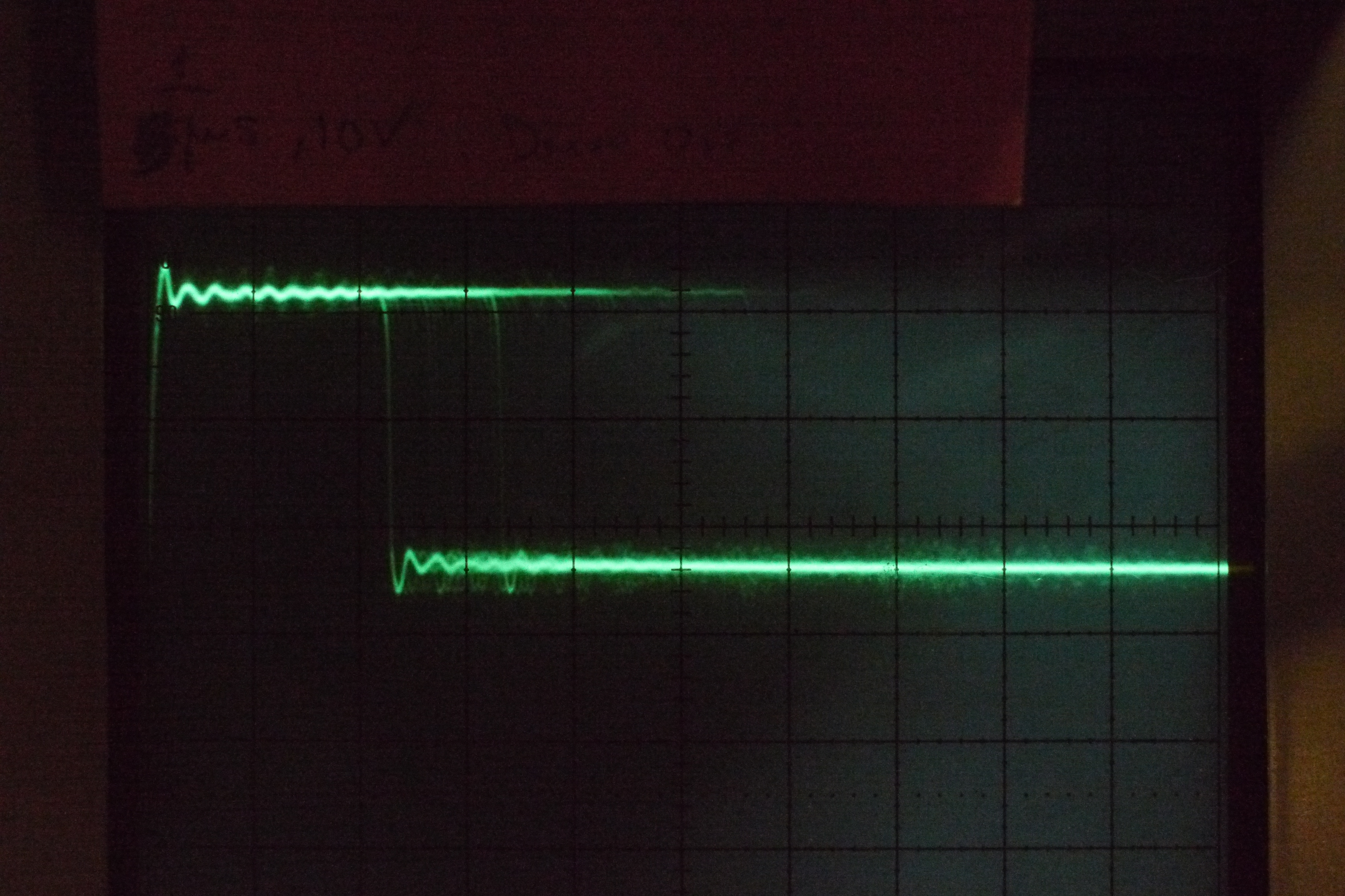
The voltage swing is ~24v, so at least that makes sense. The 5v ripple is still there. And there also seems to be a rapid variation in pulse width from about 2 to 5.5us, which I think is what you expect the microstepping to look like when the motor's running, but again, it wasn't moving when I took that.
The machine has very long, non-twisted pair, non-shielded cables. For lack of another thing to try, I bought shielded twisted pair cable to change to.
Anyone?
~Justine
-
Have you tried swapping out the motors? or even swapping the x and y for lack of another pair.
-
My guess is that you are using an ungeared extruder drive with a low steps/mm value. If that's the case, either replace the 1.8deg motor on your extruder by a 0.9deg one, or (preferably) switch to a geared extruder.
-
Thanks for the quick replies.
Jason, yes, all the X and Y motors have already been replaced. By the way, the gantry is large enough that I have two motors per axis. Still, I've swapped out all four motors, and I see the banding on both axes. They're NEMA 23 at 200 steps/rev. I did see a note on another forum that someone thought NEMA 23s run rougher than NEMA 17s, but that's quite anecdotal. I could try that next.
Hi dc42, no, it's a geared extruder (e3d Titan). This gives 410.2 steps/mm. I did try changing it to 410.0 to see if that would make a difference, but no.
I've noticed an odd Duet-specific behavior I forgot to mention previously, and that is that if I reduce the X-Y jerk to less than ~300, the toolhead stutters through curves. If I reduce it to something like 10, it's amazingly bad. But, I'm not convinced the effect is completely gone even at high jerk settings. Any thoughts on that?
1. Please run M350 without parameters, to confirm that you still have the microstepping set at x16 with interpolation, just in case another M350 command has been executed.
2. Can you relate the spacing of the bands to the amount moved per full step or per 4 full steps of either the X motor (if the banding happens on lines in the X direction), or Y motor (if the banding happens on lines in the Y direction), or the extruder?
3. If you change the extrusion width in the slicer, does the spacing of the bands change? If so, that suggests the problem is extruder-related.
4. It's normal for curves to be jerky if you set the allowed jerk to low. The whole purpose of allowing jerk is to avoid slowing the print speed down when changing the direction of motion by small angles.
-
Two more questions:
1. Does the banding occur on lines printed in all directions? It's hard to tell from your photo, but it looks like the banding may not be occurring in the direction at right angles to the one that you are focussing on.
2. What is the printer architecture: Cartesian, or CoreXY?
-
By looking at the first picture, the bottom right corner doesn't seem to have banding. The issue you are having looks more like ripple/ribbing/ghosting. I have this problem also… Lowering accel, jerk and motor current helped a lot, but I'm still struggling with it.
A couple of questions.
Does this still happen when printing cylinders?
If you print a 100x100mm cube, this issue happens right after a corner is printed or it's in the entire perimeter? -
Thanks for the help dc42:
1. Please run M350 without parameters, to confirm that you still have the microstepping set at x16 with interpolation, just in case another M350 command has been executed.
The output both with the machine sitting quiescent and while running a print is [c]Recvd: Microstepping - X:16(on), Y:16(on), Z:16(on), E:16(on):16(on):16(on):16(on):16:16:16[/c].
2. Can you relate the spacing of the bands to the amount moved per full step or per 4 full steps of either the X motor (if the banding happens on lines in the X direction), or Y motor (if the banding happens on lines in the Y direction), or the extruder?
If I run the print at 3000mm/m I get one spacing (pitch is about 1.7mm). If I run it at 5000mm/m the spacing increases noticeably (I forgot to measure that and trashed the print, but it definitely changes). I interpret this to mean that it's independent of the stepping, or at least related to it in a non-simple way.
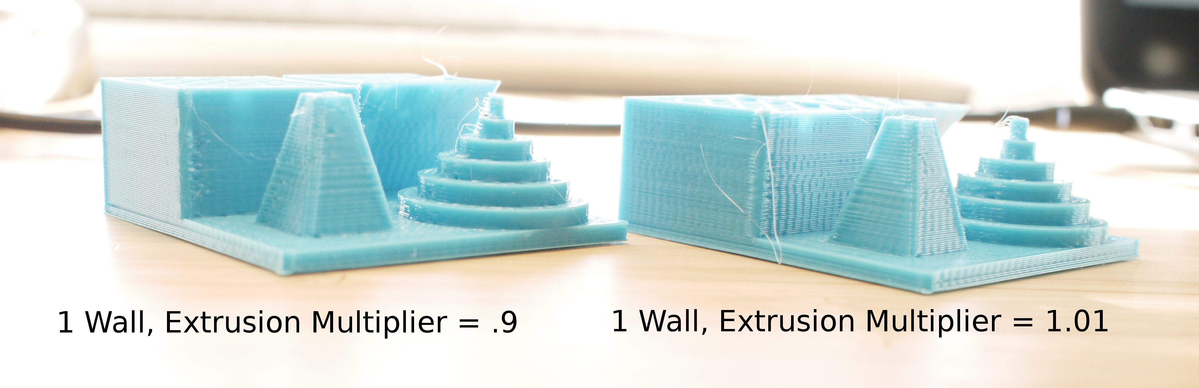
3. If you change the extrusion width in the slicer, does the spacing of the bands change? If so, that suggests the problem is extruder-related.
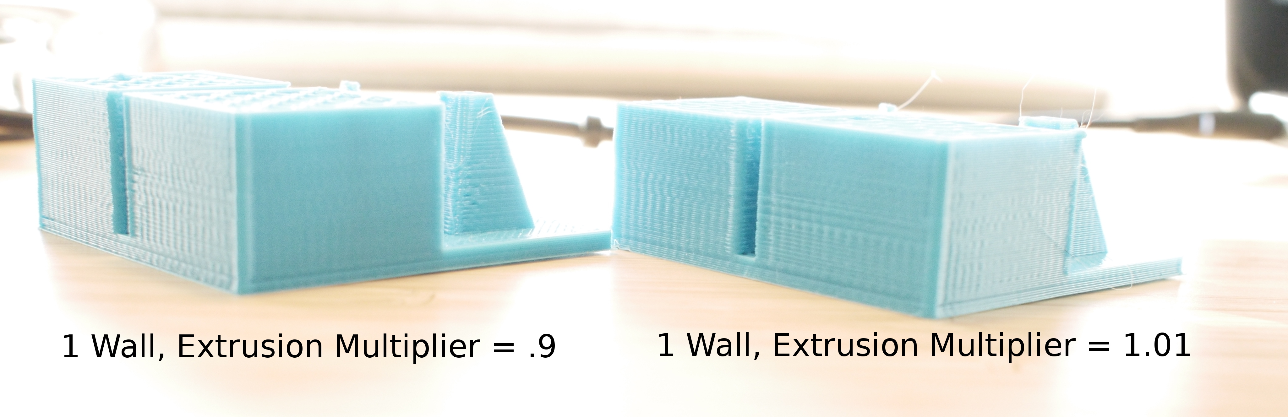
I just ran two test prints. I changed outline/perimeter shells to 1 for clarity. In both images the part on the left has the extrusion multiplier set to .9, and on the right it's 1.01 (my normal setting). Just as I'm typing this I see that you said Extrusion Width, not Multiplier, but here it is anyway. I don't see a difference in the banding. If you think extrusion width is more relevant I'll run them again:
4. It's normal for curves to be jerky if you set the allowed jerk to low. The whole purpose of allowing jerk is to avoid slowing the print speed down when changing the direction of motion by small angles.
I pointed it out because we have a TAZ 5 at work on which the jerk setting is 10, but it goes through curves perfectly smoothly even like that. I didn't quite realize that was the reason for it though. I know it isn't "true" jerk in the sense that it isn't directly affecting mm/s/s, but that's a good explanation.
1. Does the banding occur on lines printed in all directions? It's hard to tell from your photo, but it looks like the banding may not be occurring in the direction at right angles to the one that you are focussing on.
Yes, which you can also see in the new pictures above. Note on the pyramidal structure on the test prints that the banding follows the slope of the pyramid (i.e., is initiated by the turn), although the bands aren't always aligned from layer to layer. I've also printed with the part oriented 45deg from normal, and the effect looks much the same.
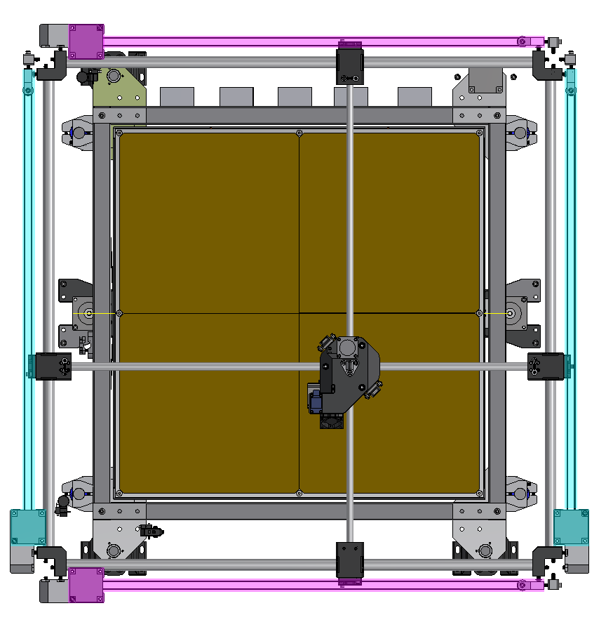
2. What is the printer architecture: Cartesian, or CoreXY?
Neither, it's a crossed-rail system similar to an Ultimaker, but the belt arrangement is different. This screenshot is highlighted to show how the motors and belts are arranged. The magenta highlighting shows the X drives, and the blue highlighting shows the Y drives:
Some photos taken during one of the above test prints:


Those crazy springs pulling up on the carriages negate sag in the outer shafts (that's another story). Their presence doesn't effect the banding; it's exactly the same with and without them.
Pardon the mess of wires in those pictures. The whole "control panel" setup is a temporary kluge until I have the machine working well enough to print a proper panel for all the electronics and controls.
Thanks again for your attention.
~Justine
-
Hi Martin, I admit it does look suspiciously like severe ringing, but changing the acceleration (and jerk) all through an extreme range of values doesn't effect it at all. What's more, there's no sufficiently slow speed that will make it go away. It's there on cylinders as well. With a test cube it's the whole perimeter, but its amplitude is confusingly inconsistent. In may sometimes be conflated with actual ringing, but I've convinced myself it's something different.
-
Jerk is set in mm/min in RRF just like all the other speeds, but some other firmwares use mm/sec for jerk. So 10 on your Taz 5 may correspond to 600 in RRF.
-
Ahhhhhh aha, okay, thank you dc42.
By the way, I just put the scope on my Makergear M2 and what I see is more or less consistent with what I'm getting on the Duet, so facepalm to me for not understanding the stepper waveform.
Anyway, the issue with the banding persists. I realized I have some NEMA 17s laying around. I'm going to swap the two X-axis motors with these and see what happens.
-
Well, I just tried switching the X-axis motors to NEMA 17s and the banding is exactly the same. Still quite stuck and seeking ideas.
-
If it was related to motors steps, the spacing of the bands would be constant. So I think the print head is vibrating, and something is maintaining the vibration. A constant vibration frequency will cause the bands to be more widely spaced when you increase the printing speed.
-
Huh, I'll try a print with the cooling fan off. Maybe it's exciting a resonance.
-
Hello, I have the same Issue on my P3Steel with a Duet WiFi, so I thought I'd share my experiences. For me, they're more noticeable along the Y-Axis (maybe a problem with the bed?) than along the X-Axis, but it's still there on both.
I too have an e3d Titan Extruder (with a 0.9° Stepper) and played around with the extrusion, but it didn't change much.
I tried various acceleration, jerk and speed settings. Also I don't seem to be getting those ripples on curved surfaces.
I also tried printing without any fan running on the Printer (Had to unclog my Hotend after that…) but it didn't help.
Another thing I tried was putting astrosyn dampeners on all motors, but that also didn't help.
Then I tried something "just for fun" and replaced the duet WiFi with an Ultimachine RAMBo 1.3, running the latest Marlin Firmware with the same Motion settings that I settled on in the Duet Firmware. Now it's still happening but its much less noticeable. On the Duet print I could easily feel the ripples when running over the surface with my fingernail, and on the RAMBo print I can't.
-
Would be interesting to swap the drivers, if you can, trying DRV8255, TMC2100, A4988…
-
After an extended struggle, I just cracked an issue that looks like this on my D-Bot (CoreXY). The issue was GT2 teeth hitting smooth idlers and the solution was a half twist in the belt so the smooth surface would contact the idlers instead of the teeth. Note: the pitch of the defect also didn't align perfectly with the GT2 teeth so I think the interaction of the teeth on the idler is more complex than a simple 1:1 with the surface defects. The album has all of the details including the (many) things that were ruled out before arriving at a solution: https://imgur.com/a/kb2nE
Here's the side by side shot showing the result of the belt twist:

I also posted this to Reddit. If you're interested the discussion links are:
https://www.reddit.com/r/dbotcorexy/comments/7d1s8j/vertical_surface_ripples_banding_waves_solved/
https://www.reddit.com/r/3Dprinting/comments/7d1pqe/vertical_surface_ripples_banding_waves_solved/I hope it helps!
-
@denos. That's interesting. What diameter are your idlers? I ask because I don't have an issue running the toothed side of the belt over my idlers although I know that technically it's not ideal, but they are quite large diameter. It may also be that my 4Kg of mass that I throw around just damps everything out
")
-
I'm not at home at the moment but they're small – similar in size to the diameter of my 16T pulleys. A larger idler might help. Here is some additional context from a response I posted on Reddit:
"Keep in mind that this is a black, glossy filament that was printed too hot (making it less viscous / more susceptible to deflection) and the light has to be oriented just right to catch the surface ripples.
It is worst when rotating prints by 45 degrees so each stepper motor is isolated and printing at higher speeds. In a typical orientation (flat surfaces parallel to the X and Y axis), the effect is more subtle and may just appear as slight surface texture (I suspect this occurs if the motors are offset by half a step). On cylindrical surfaces it looks more like moire or diagonally arcing defects.
I didn't notice the issue with PLA printed at the low temperatures and speeds or using lighter colors. It can also be alleviated by loosening the belts at the expense of jerk / acceleration artifacts with higher speeds.
It only became a problem as I tightened the belts down while testing the upper end of the speed range for the D-Bot (150 - 200 mm/s). Then it drove me nuts..." -
That may be why I've never had an issue then. Yours will be about 9mm diameter whereas mine are around 18mm. That and the fact that as I said, my 4Kg mass tends to dampen out any vibrations.