Controlling L298N w/ Duet 2 Wifi
-
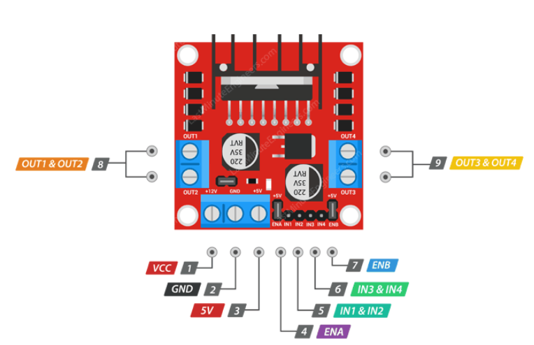
I've got the following L298N module (below) that I'm using to control the polarity on some linear actuators. What's the correct way to control these with a Duet 2 wifi? Could I run IN1 & IN2 to heater4 & heater5 pins, respectively, then use the following:
M42 P0 C"exp.heater4"        ;IN1 on Heater 4
M42 P0 S1                              ;Set Heater 4 to HIGH
M42 P1 C"exp.heater5"       ;IN2 on Heater 5
M42 P1 S0                             ;Set Heater 5 to Low
This seems inefficient/wrong and I'm guessing there's a better way to do that. Some help would be much appreciated, thanks!
-
 undefined JRCL marked this topic as a question
-
@JRCL You could use any GPIO pin with it. (perhaps need a level shifter board)
Heater and fan terminals only switch between VCC (12-24V) to GND, that's not what you want here.Depending on your control board, you can jumper some fan ports to 5V.
That's better and you might need to add a pullup resistor (10k-ish) or activate the internal pullup (not possible with all Duets)
Anyway, the logic is reversed and you want to add "!" to invert the logic or "!^" to also activate the internal pullup if possible. -
This post is deleted! -
@o_lampe Thanks for the insight! Just some additional clarification
So other than the logic being wrong, I need to either jumper 5V to the fan ports and use those instead, or add in a level shifter board so I can drop the 12/24V heater signal down?
However, using the M42 command to set the pins to HIGH and LOW is the correct way to do it. I just need to make sure the logic is proper.
-
@JRCL you need to use M950 to configure the port as a GPOUT port, then use M42 to control it.
The L298N accepts TTL-level input voltages, so it can be driven form 3.3V signals such as the exp.heaterN pins on the Duet 2 expansion connector. However, at reset these pins are all pulled high at startup by the internal pullup resistor in the microcontroller. So you should probably invert the pin name in the M950 command in order that when you send the MN950 commands, the output doesn.t change.
You may also want to drive the Enable input of the L298N from another output of the Duet. In this case you should not invert that output, but you should connect a pulldown resistor of about 4.7K between that output and ground so that the L298N remains disabled at power up.
-
undefined JRCL has marked this topic as solved