bad Vssa - after moving printer one room
-
I moved my printer to another room checked the cables and turned it on.
I gave the signal to home but there was just a summing of the motors.
After another check on the wiring with no issue found and a power cycle the motors moved nominal.
Unfortunately now the temperature is shown as 2000C and I get the 'VSSA fault - check your thermistor cable' error message.
I have a Duet 3 Mini 5+ Ethernet v1.0 connected to a Raspberry Pi 4.
The thermistor have a resistance of 107 kΩ measured at room temperature at the connectors.
For tests I first removed the thermistor cables and then all other cables but the 24V power and SBC connection but still got the error message.The error message for both thermistors is the same:
M308 S1
Sensor 1 (Hotend) type Thermistor using pin temp1, reading 2000.0, last error: bad Vssa, T:100000.0 B:4725.0 C:7.06e-8 R:2200.0 L:5 H:-5
M308 S0
Sensor 0 (Bed) type Thermistor using pin temp0, reading 2000.0, last error: bad Vssa, T:100000.0 B:3950.0 C:0.00e+0 R:2200.0 L:5 H:-4The resistance between VSSA pin and the thermistor pin are 3.81 kΩ and when powered off.
When powered on the voltage difference is 3.14 V.The resistance of the PTC fuse is 3.7 Ω.
The voltage drop if turned on is also near zero.The voltage drop from the Thermistor - VSSA Pin to IO - GND Pin is 0 V.
The voltage drop from the Thermistor 0/1/2 Pin to IO - GND Pin is 3.3 V.Some further measurements:
R54 = 8.6 kΩ
R53 = 8.8 kΩ
R52 = 8.1 kΩR60 = 2.2 kΩ
R61 = 2.2 kΩ
R62 = 2.2 kΩR50 (right from C110) = 29.4 Ω
R51 (above C119) = 1.6 kΩ [should be 4k7]R66 (left from C121) = 10 kΩ
Moreover the out_2 is powered on without being defined in the config.g
The voltage is at 14 V.
If I define it as output for the heater it is turned of after fully booting.Should I replace R51 or could that happen because it is parallel to another resistor?
And is it normal that the out_2 is initially on?Thanks in advance.
-
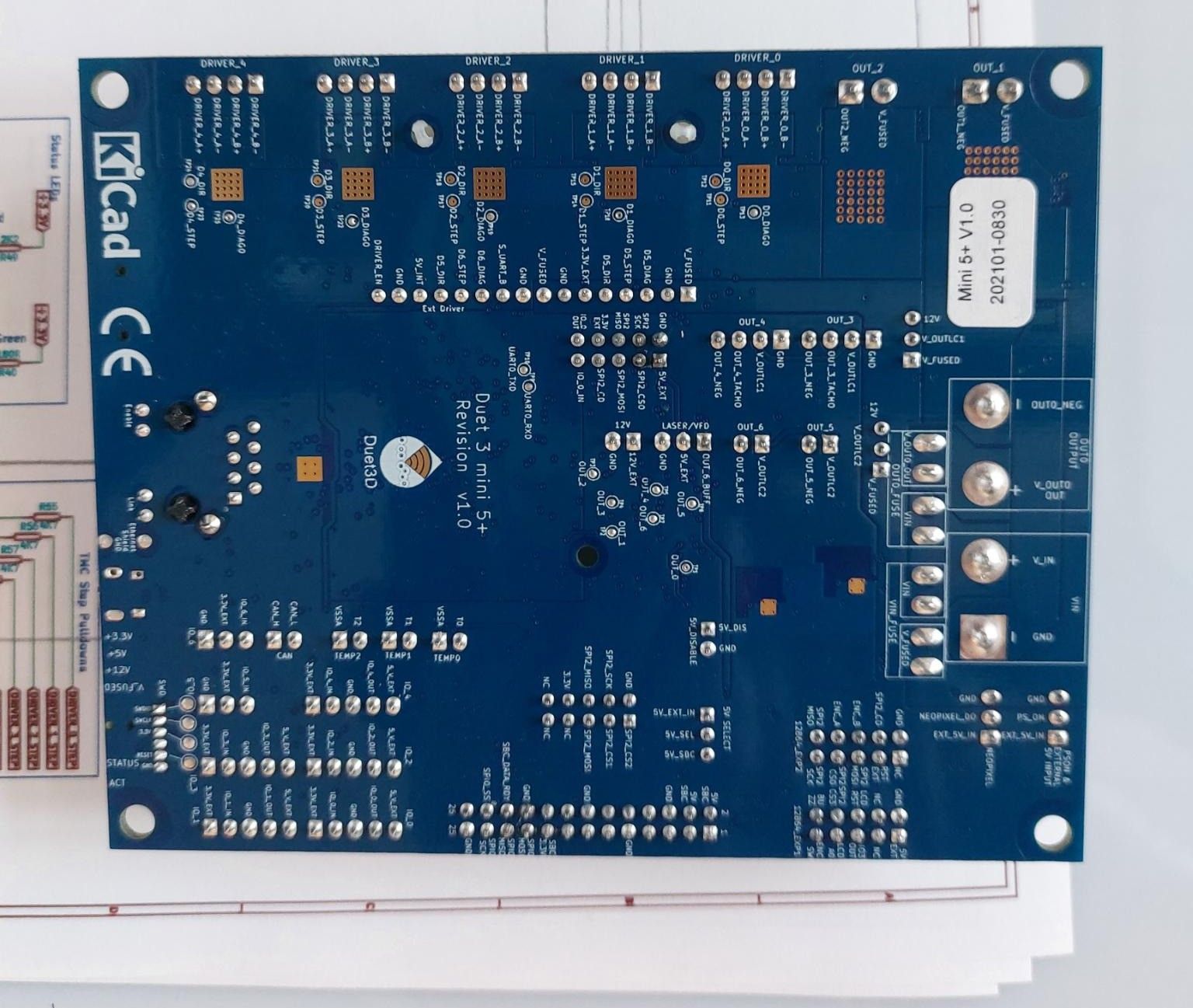
Can you get some clear photos of the board?
Do you get any errors if you disconnect everything except USB for power and terminal? -
@Phaedrux thank you for replying.
I have attached pictures of the board.
I can check how it reacts with just USB tomorrow.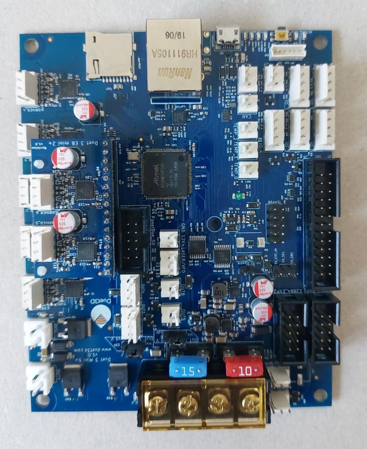
-
When and where was it purchased?
-
After me making the USB connection a bit more cumbersome then it need to be the result is unfortunately still the same:
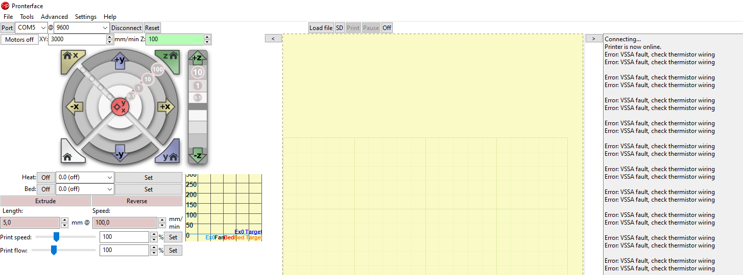

I purchased it from https://www.dold-mechatronik.de/ in December of 2021.
-
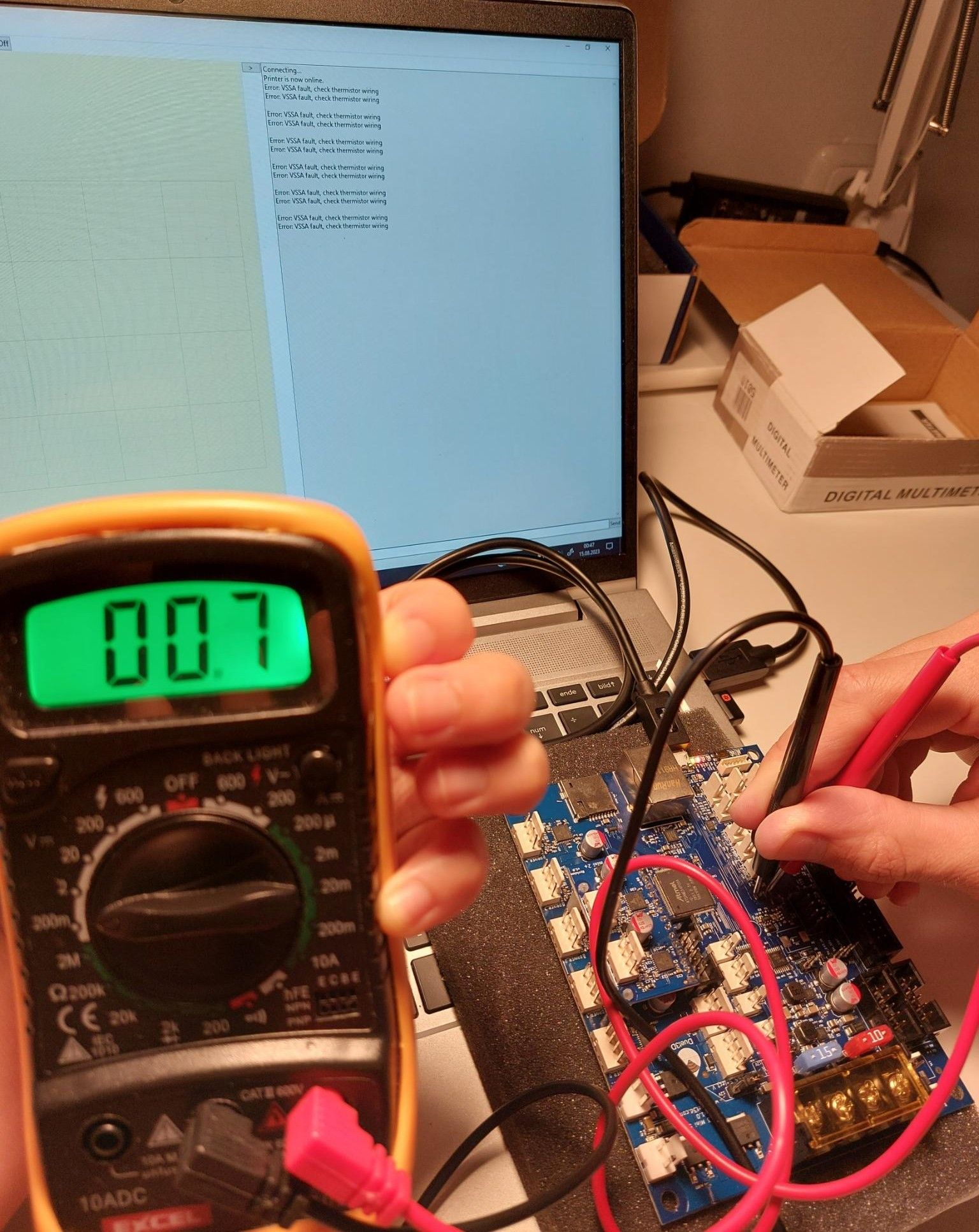
@nkunst while it is reporting Vssa fault, can you measure the voltage across the VSSA fuse using a multimeter? It's the green component with bF printed on it.
-
@dc42
Sorry for the delay.
With 0.7 mV it is negligible.
When I turn of the hardware it is zero as it should be.
I tested that to be sure I have contact through the oxide layer and are not measuring statics.
-
@nkunst thanks. It looks like either the Vssa ADC channel has failed (which isn't likely unless there has been a more general ADC failure), or the 10K resistor R83 that connects Vssa to the MCU is open circuit.
-
@dc42
I measured the following resistors.
The connect comment is according to the Duet3_5+_Ethernet_Schematic_v1.0.pdfR38 = 3.8 kOhm (connected to OUT_3_TACHO)
R83 = 4.7 kOhm (connected to OUT 2 MOSFET CONTROL)
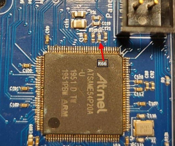
R66 = 10 kOhm (connected to VSSA and VSSA_MON)I marked which resistor I assumed is R66 since it is a bit blurry:
Additionally I run the M122 command to get some 'test' for the ADC.
Here is an extract from it:SENDING:M122
=== Diagnostics ===
RepRapFirmware for Duet 3 Mini 5+ version 3.4.1 (2022-06-01 21:06:56) running on Duet 3 Mini5plus Ethernet (SBC mode)MCU revision 3, ADC conversions started 74546, completed 74546, timed out 0, errs 0
Step timer max interval 1000521
MCU temperature: min 26.1, current 29.9, max 29.9
Supply voltage: min 1.5, current 3.2, max 3.3, under voltage events: 0, over voltage events: 0, power good: no -
@nkunst yes that's R66. I suggest you look at the lower end of it using magnification. There is a shadow at the bottom of it that could indicate that it is not soldered to the pad. Or you could try measuring the resistance between the top end of R66 and the bottom end of C121 to its right, which the bottom end of R66 should be connected to.
Do the VIN and 12V voltages read correctly in M122?
-
Dear @dc42 ,
the M122 from my last message was measured while just being connected to the USB cable.
In that case 3.3 V is possible.I connected it to my 24 V source (which location is the reason for my late reply).
As seen in the extract below the ADC also reads 24 V.SENDING:M122
=== Diagnostics ===
RepRapFirmware for Duet 3 Mini 5+ version 3.4.1 (2022-06-01 21:06:56) running on Duet 3 Mini5plus Ethernet (SBC mode)MCU revision 3, ADC conversions started 172380, completed 172378, timed out 0, errs 0
Step timer max interval 779
MCU temperature: min 30.9, current 30.9, max 31.3
Supply voltage: min 24.1, current 24.2, max 24.2, under voltage events: 0, over voltage events: 0, power good: yesI measured the R66 and the other relevant resistors from other pins as seen below:
This points I marked in the attached picture:
1 -> VSSA
2 -> THERMISTOR_0
3 -> THERMISTOR_1
4 -> THERMISTOR_2
5 -> VDDANA7 -> VSSA_MON
8 -> VREF_MON
9 -> GNDANA
10 -> VSSA11 -> Temp_0
12 -> Temp_1
13 -> Temp_214 -> R51 VREF_MON side
15 -> R51 VSSA side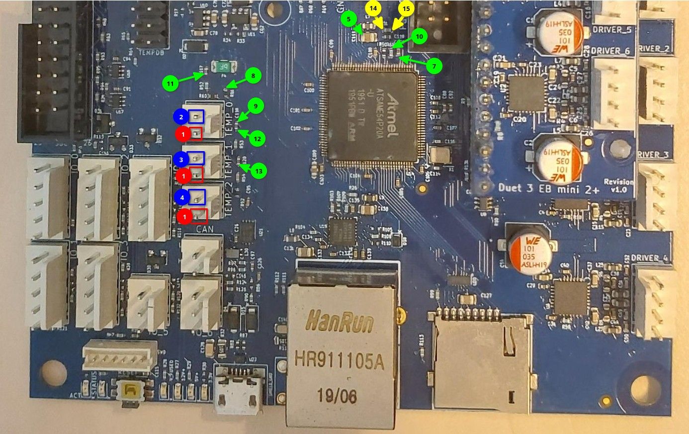
R66: 7-8 = 11.7 kΩ (nominal 10 kΩ)
PTC fuse: 9-10 = 3,4 Ω
R50: 5-8 = 29.4 Ω (nominal 27 Ω)
R54: 2-11 -> 8.03 kΩ (nominal 10 kΩ)
R53: 3-12 -> 8.44 kΩ (nominal 10 kΩ)
R52: 4-13 -> 7.54 kΩ (nominal 10 kΩ)R60: 2-8 -> 2.15 kΩ (nominal 2.2 kΩ)
R61: 3-8 -> 2.19 kΩ (nominal 2.2 kΩ)
R62: 4-8 -> 2.12 kΩ (nominal 2.2 kΩ)From this the only abnormal resistor was R51:
R51: 8-10 = 1.64 kΩ (nominal 4.7 kΩ)thermistor pins
1-2 = 3.8 kΩ (nominal R51 + R60 = (4.7 + 2.2) = 6.9 kΩ)
1-3 = 3.8 kΩ (nominal R51 + R61 = (4.7 + 2.2) = 6.9 kΩ)
1-4 = 3.8 kΩ (nominal R51 + R62 = (4.7 + 2.2) = 6.9 kΩ)Circuits:
1-10 = 2.4 Ω
1-14 = 0.396 kΩ (with resistor in between)
1-15 = 3.5 Ω
8-14 = 5.1 Ω
8-15 = 1.14 kΩ (with resistor in between)Can a faulty R51 cause this issue?
-
TL/DR:
The ADC seems ok but R51 is odd. -
@nkunst an open circuit R51 could cause the problem. However, I suspect your multimeter is reading a current path through the VSSA fuse, the components between +3.3V and ground, and R50.
To check whether an open circuit R51 could be the problem, try putting a jumper across an unused thermistor input and see if the problem goes away.
-
@dc42 I put an jumper on a non used thermistor but still got an error report.
In a moment of thoughtlessness I unsoldered the R51 to be sure it is good.
It is but I need to solder it on again which is a bit more difficult as expected.
Due to location issues this will happen earliest of Friday. -
@dc42
Placed R51 back on PCB -> measured resistance -> proper solder joint -> still bad VSSA
Extra solder paste to R50 & R66 -> still bad VSSAThought a moment, resistors seem to be ok, ADC according to input voltage reading too, connection to chip still unchecked:
Flux on Atmel chip contacts next to R66 -> No VSSA error anymore but weird temperature readings which are changing when resistor connected
Add solder paste to Atmel chip contacts -> temperature readings are correct againThank you for your help.
I am enjoying a working motherboard again
-
@nkunst I'm glad you solved it! To confirm, you think the issue was a bad solder joint on the microcontroller?