MBL Issues on Cartesian Printer w/ D3Mini5+
-
Hey guys. Finally hit wits end with this Duet board - can't get mesh bed leveling working properly no matter what I do, and it worked fine with the old Marlin control board I had in there before.
If I home the machine and load the heightmap, I can paper check the middle of the bed at Z0 and it's fine, but when the head moves left, the nozzle gets further away, opposite happening when it moves right.
The printer is a converted Robo 3D R1+. It's a bed slinger with dual Z screws. This one has a magnetic glass bed, and the Z screws are connected to independent outputs on the Mini 5+. The head assembly is my own design using a Hemera XS and a BLTouch probe. I've got G32 working to probe each side of the bed already to level the screws.
The board is running RRF 3.4.6 stable release.
Config.g
; Configuration file for Duet 3 Mini 5+ (firmware version 3.3)
; executed by the firmware on start-up
;
; generated by RepRapFirmware Configuration Tool v3.3.16 on Tue Aug 29 2023 17:10:44 GMT-0500 (Central Daylight Time)

; General preferences
G90                                          ; send absolute coordinates...
M83                                          ; ...but relative extruder moves
M550 P"R1Plus"                               ; set printer name

; Network
M552 S1                                      ; enable network
M586 P0 S1                                   ; enable HTTP
M586 P1 S0                                   ; disable FTP
M586 P2 S0                                   ; disable Telnet

; Drives
M569 P0 S0                                   ; physical drive 0 goes backwards
M569 P1 S1                                   ; physical drive 1 goes forwards
M569 P2 S1                                   ; physical drive 2 goes forwards
M569 P3 S1                                   ; physical drive 3 goes forwards
M569 P4 S0                                   ; physical drive 4 goes backwards
M584 X0 Y1 Z2:3 E4                           ; set drive mapping
M350 X32 Y32 Z16 E16 I1                      ; configure microstepping with interpolation
M92 X160.00 Y160.00 Z800.00 E397.00          ; set steps per mm
M566 X900.00 Y900.00 Z60.00 E300.00          ; set maximum instantaneous speed changes (mm/min)
M203 X12000.00 Y12000.00 Z1200.00 E2400.00   ; set maximum speeds (mm/min)
M201 X2000.00 Y2000.00 Z40.00 E5000.00       ; set accelerations (mm/s^2)
M906 X900 Y900 Z900 E800 I85                 ; set motor currents (mA) and motor idle factor in per cent
M84 S30                                      ; Set idle timeout
M566 P1                                      ; set jerk policy to 1 (default 0)

; Axis Limits
M208 X0 Y0 Z-2 S1                            ; set axis minima
M208 X209 Y245 Z200 S0                       ; set axis maxima

; Endstops
M574 X1 S1 P"io0.in"                         ; configure switch-type (e.g. microswitch) endstop for low end on X via pin io0.in
M574 Y1 S1 P"io1.in"                         ; configure switch-type (e.g. microswitch) endstop for low end on Y via pin io1.in
M574 Z1 S2                                   ; configure Z-probe endstop for low end on Z

; Dual Z-Screw Leveling Config
M671 X0:209 Y122.5:122.5 S10                 ; define z-screw pivot locations

; Filament Run-out Sensor
M591 D0 P1 C"!io2.in" S1                     ; configure active low filament run-out switch for drive 0 aka E0

; Z-Probe
M950 S0 C"io3.out"                           ; create servo pin 0 for BLTouch
M558 P9 C"io3.in" H3 F600:60 T6000 B1        ; set Z probe type to bltouch and the dive height + speeds
G31 P500 X-26.17 Y-53.21 Z1.45               ; set Z probe trigger value, offset and trigger height
;M557 X0:209 Y0:245 S30                       ; define mesh grid - Original
;M557 X0:182 Y0:191 S45                       ; define mesh grid - maxima minus probe offsets
M557 X0:182 Y0:191 P4:4                       ; define mesh grid - 4x4 grid
M376 H20                                     ; define bed leveling taper-off height (40x Error Max)

; Heaters
M308 S0 P"temp0" Y"thermistor" T100000 B4066 ; configure sensor 0 as thermistor on pin temp0
M950 H0 C"out0" T0                           ; create bed heater output on out0 and map it to sensor 0
;M307 H0 B0 S1.00 R0.30                      ; disable bang-bang mode for the bed heater and set PWM limit - ORIGINAL
;M307 H1 B0 S1.00                            ; disable bang-bang mode for heater E0 and set PWM limit - ORIGINAL
M140 H0                                      ; map heated bed to heater 0
M143 H0 S120                                 ; set temperature limit for heater 0 to 120C
M308 S1 P"temp1" Y"thermistor" T100000 B4267 ; configure sensor 1 as thermistor on pin temp1
M950 H1 C"out1" T1                           ; create nozzle heater output on out1 and map it to sensor 1
M143 H1 S280                                 ; set temperature limit for heater 1 to 280C
M301 H0 P28.65 I2.39 D86.01                  ; set bed stock PID values from original Robo3D R1+ Firmware
M307 H1 R4.371 K0.489:0.321 D2.16 E1.35 S1.00 B0 V12.3 ; set E0 PID Values

; Fans
M950 F0 C"out3" Q500                         ; create fan 0 on pin out3 and set its frequency
M950 F1 C"out4" Q500                         ; create fan 1 on pin out4 and set its frequency
M106 P0 S0 H-1                               ; set fan 0 value. Thermostatic control is turned off
M106 P1 S1 H1 T45                            ; set fan 1 value. Thermostatic control is turned on

; Tools
M563 P0 S"Revo Hemera XS" D0 H1 F0           ; define tool 0
G10 P0 X0 Y0 Z0                              ; set tool 0 axis offsets
G10 P0 R0 S0                                 ; set initial tool 0 active and standby temperatures to 0C

; Cabinet LED's
M950 P1 C"out5"                              ; enable output5 for left side LED strip
M950 P2 C"out6"                              ; enable output6 for right side LED strip

; Custom settings are not defined

; Miscellaneous
M564 H1 S1                                   ; Disallow unhomed moves & beyond axis movements
M501                                         ; load saved parameters from non-volatile memory
bed.g
; bed.g
; called to perform automatic bed compensation via G32
;
; generated by RepRapFirmware Configuration Tool v3.3.16 on Tue Aug 29 2023 17:10:44 GMT-0500 (Central Daylight Time)
G90 ; absolute positioning
G28 ; home
G30 P0 X0 Y122.5 Z-99999 ; probe near a leadscrew, half way along Y axis
G30 P1 X182 Y122.5 Z-99999 S2 ; probe near a leadscrew and calibrate 2 motors
G1 X104.5 Y122.5 F6000  ; go to middle of bed
G30                     ; home Z by probing the bed
G90                     ; absolute positioning
homeall.g
; homeall.g
; called to home all axes
;
G91                     ; relative positioning
G1 H2 Z5 F6000          ; lift Z relative to current position
G1 H1 X-215 Y-250 F1800 ; move quickly to X and Y axis endstops and stop there (first pass)
G1 H2 X5 Y5 F6000       ; go back a few mm
G1 H1 X-215 Y-250 F360  ; move slowly to X and Y axis endstops once more (second pass)
G90                     ; absolute positioning
G1 X104.5 Y122.5 F6000  ; go to middle of bed
G30                     ; home Z by probing the bed
G91                     ; relative positioning
G1 Z5 F6000             ; lift Z relative to current position
G90                     ; absolute positioning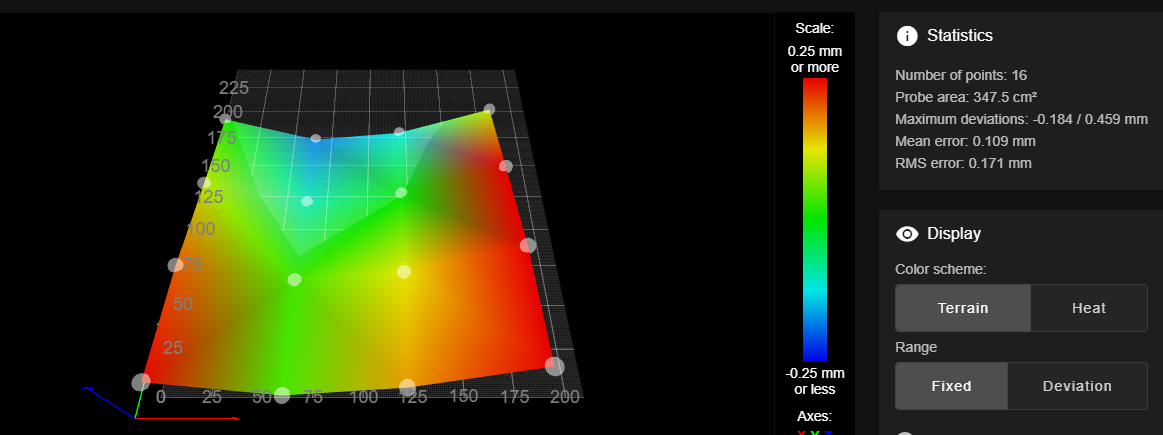
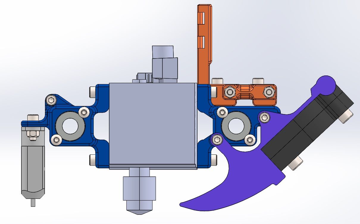
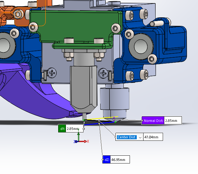
Side view of carriage.
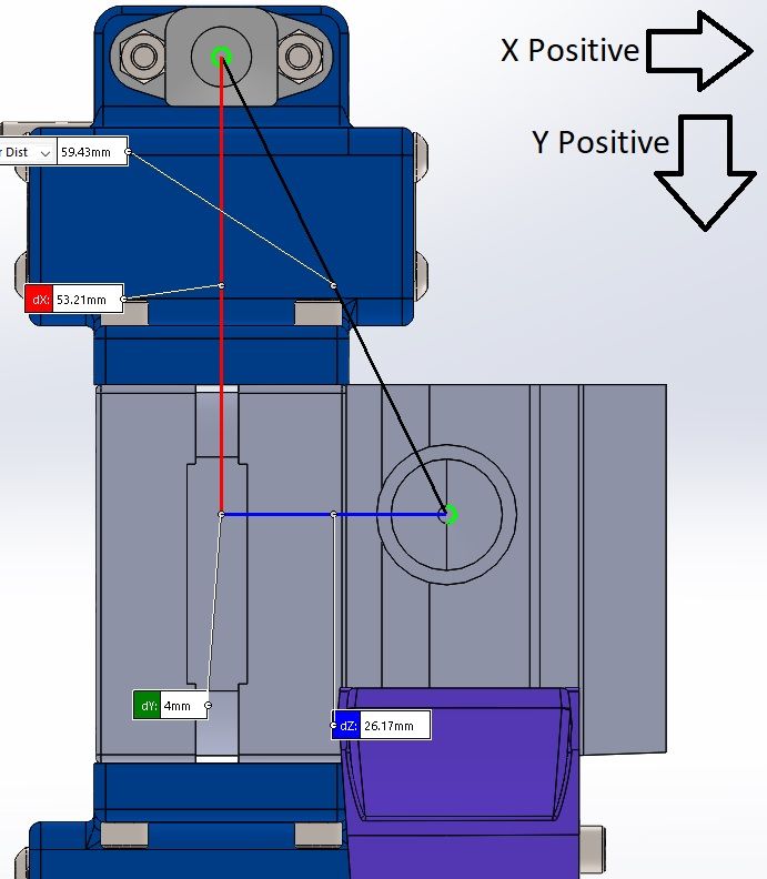
Offset measurements.
-
@WindDrake thanks for providing good information in your post.
Here are two things to check:
-
If you run G32 multiple times, the reported initial deviation should converge to a low value. Does it? If instead the reported initial deviation increases then the configuration needs to be adjusted.
-
Measure the trigger height of the probe at a few different places on the bed, to check that it is consistent. Also check that it is the same whether you move to the probe point in a positive or negative X direction.
Duet WiFi hardware designer and firmware engineer
Please do not ask me for Duet support via PM or email, use the forum
http://www.escher3d.com, https://miscsolutions.wordpress.com -
-
Thanks for the pointers. Here's 10 consecutive G32's.
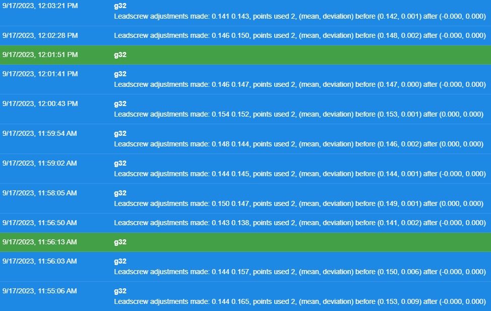
Looks like the repeatability is under 0.01mm, around 0.007mm.
I wrote a bit of gcode to probe the bed in a cross shape, basically each corner plus the middle, five times and repeat back the trigger heights to check for repeatability.
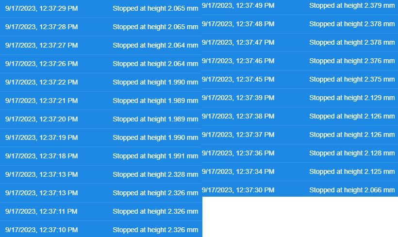
Deviation at each probe point looks like <0.005mm.
I'd say the machine is pretty repeatable... So not real sure where it's all going wrong, here.
-
Went to higher feedrate (20mm/sec instead of 2mm/sec) probing on a 10x10 mesh, here's the result.
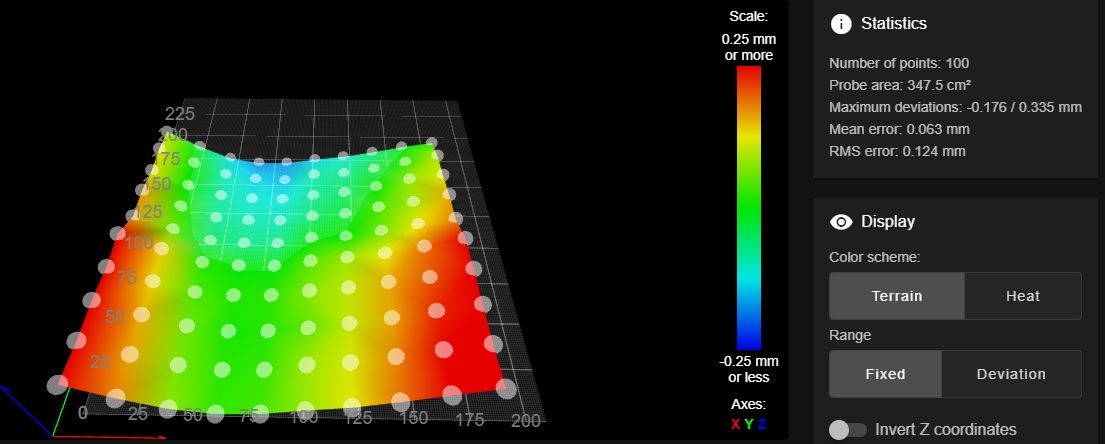
I noticed that the high spots are effectively lower than they were before, and the low end has remained the same (within 0.002mm). Makes me wonder some. Still unable to print, as there are sections far too close or far away to get the first layer to go down properly.
-
@WindDrake could the bed magnets be interfering with the trigger height of the BLTouch? We know that the magnetic field from some types of bed heater can interfere with BLTouch, so perhaps bed magnets can too.
To measure the real trigger height, use G30 S-1 to probe until it triggers. Then measure the height of the nozzle above the bed, either using feeler guages, or by commanding Z down a small amount at a time until the nozzle touches the bed (you may need to change your M208 setting to allow slightly negative Z).
Duet WiFi hardware designer and firmware engineer
Please do not ask me for Duet support via PM or email, use the forum
http://www.escher3d.com, https://miscsolutions.wordpress.com -
@dc42
I'll try re-probing the bed and skipping the red areas of the heatmap. Those bed magnets are pretty powerful, so that would make a lot of sense. I forgot that the BLTouch was hall based.Should get a chance to check this tonight. I wonder if decreasing the sensitivity would help. Hm.
-
@dc42
I got a chance to do some testing, and keeping away from the magnets doesn't seem to help at all. Trigger heights were all over the place when testing using G30 S-1. So, I hooked the nozzle probing back up and ran a 4x4 grid with it.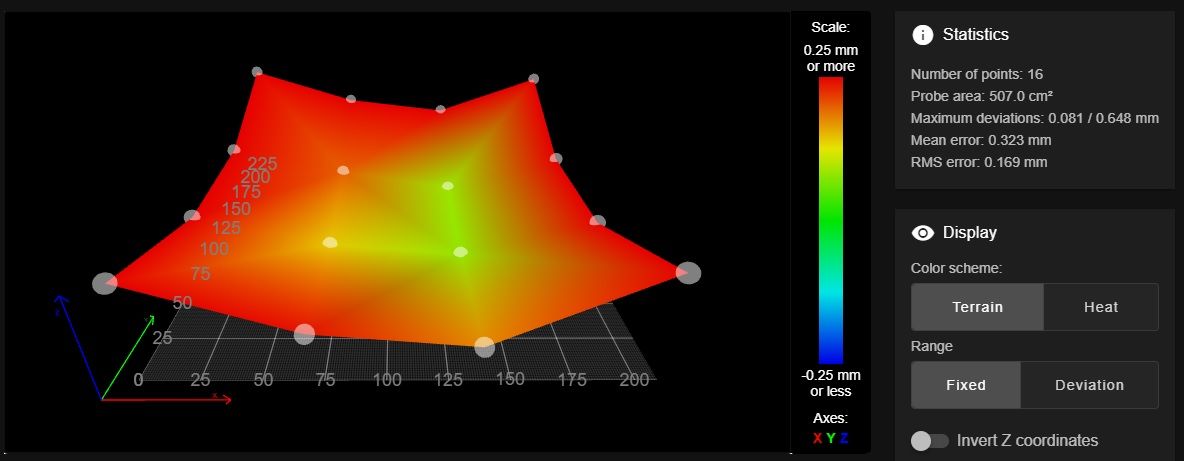
Weird as it looks, I ran a test layer with it, and it looks great. The printer is actually printing now with no headache.
It very much looks like I'm going to be picking up a CRTouch and converting to that, since these magnets appear to be a problem. Thanks for your help, and I'll report back once I get a chance to test with the new probe.
-
Got the CRTouch today, and here's the probemap.
Biggest thing I'm noticing is that the max/min deviations have shifted Z-Negative compared to the BLTouch.
Otherwise, the same issue persists.
-
Spent some time with this and a dial indicator to try and figure out what in the world is going on.
Come to find out it was mechanical, not electrical. The Y-Axis (bed) rails were badly worn (7.92mm, way out of spec..) and the original pillow blocks & dual LM8UU bearing config wasn't doing a good job of keeping things from wiggling around.
I ended up replacing the rods with proper hardened and ground linear rods, as well as redesigning the pillow blocks to use an LM8LUU paired with an LM8UU for better support. This fixed the mechanical wiggle, but the weight of the bed applying cantilever force to the pillow blocks was still moving things slightly, and the Y-Axis difference between the probe and nozzle were making this impossible to account for.
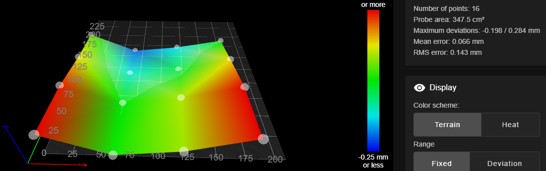
So, I redesigned my carriage assembly to put the BLTouch directly inline with the nozzle, no more Y-Axis offset.
And here's the probemap.
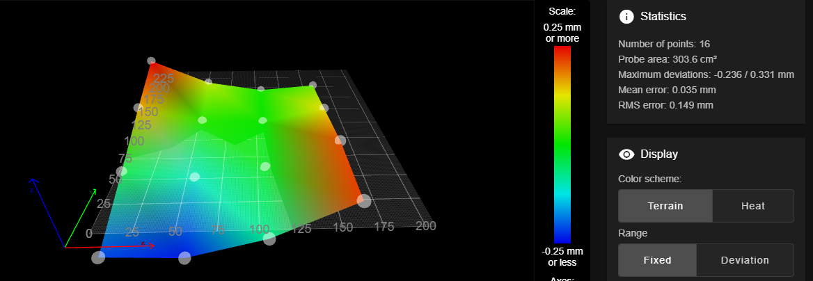
I've now successfully printed several test objects around the max size of the bed without issue.
Big thanks to @dc42 his help, and for getting me thinking if those trigger heights were real or not. That got me down the path of challenging the mechanical on this.
-
 undefined Phaedrux marked this topic as a question
-
undefined Phaedrux has marked this topic as solved