CNC Pendant Wiring Schematic
-
Hi everybody,
I am planning to build a CNC pendant according to this documentation : https://docs.duet3d.com/en/User_manual/Connecting_hardware/IO_CNC_Pendant
I will also use the panelDue.
I have made this schematic after reading the readme and the documentation, could you confirm that this is correct ?
I am not sure about the panel due passthrough.... Don't understand really what is in the actual documentation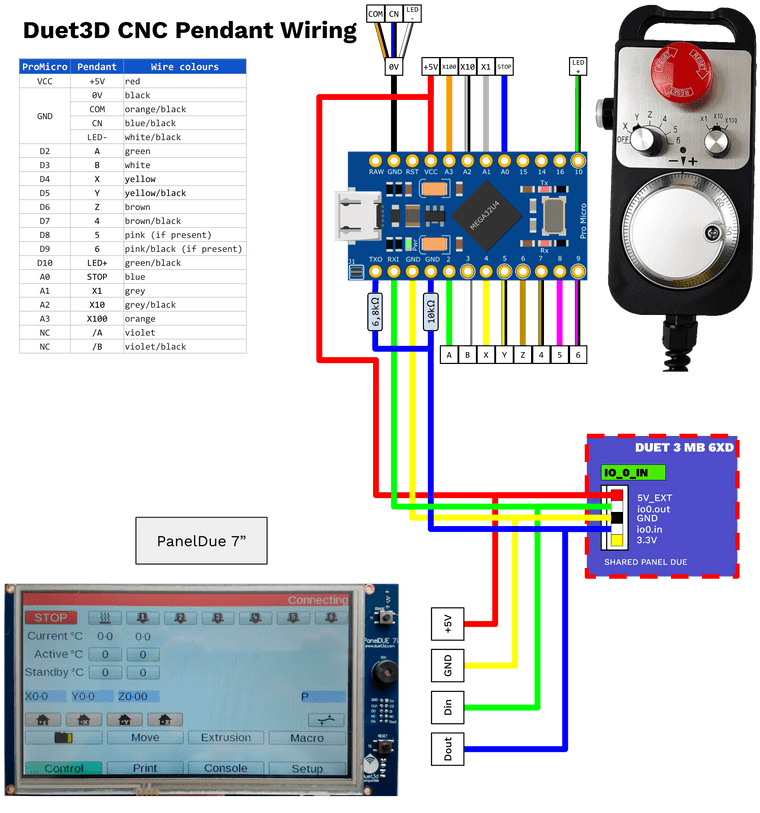
Thank you for your answer !
JeffPS : If you want the svg to complete the documentation and the github. tell me (after correction if needed
 )
) -
@jeffouille Nice! I'll check it over as best I can. It's been on my to-do list to draw a schematic/wiring diagram for this for a long time (since 30 May 2020, in fact!). If it's okay, do you mind if I take your diagram and add it to the page?
Edit: Just saw your message at the end of the page. Thanks, yes, the svg would be handy.Ian
Bed-slinger - Mini5+ WiFi/1LC | RRP Fisher v1 - D2 WiFi | Polargraph - D2 WiFi | TronXY X5S - 6HC/Roto | CNC router - 6HC | Tractus3D T1250 - D2 Eth
-
@droftarts here is the link for the svg : https://drive.google.com/file/d/1mnaXqU4zVAt4ciulPTDM1ZS2i1TMj-y_/view?usp=sharing
Hope everything is good in this schematic
-
@jeffouille I've had a good look, and as far as I can tell your schematic is correct.
There is a little confusion about the naming of the TX and RX pins on the Arduino Pro Micro: it seems TX is pin 1, and RX is pin 0, and some wiring diagrams label these as
TXI/TX1orRXO/RX0(usingIandOrather than1and0) when it should beTXO("transmit/output") on pin 1, andRXI("Receive/input") on pin 0; eg https://learn.sparkfun.com/tutorials/pro-micro--fio-v3-hookup-guide/hardware-overview-pro-micro. Even @dc42 refers toRX0on the Wiki and Github pages, when it isRXIin his images! But I can't see any boards for sale where it is visibly the other way around; they are all markedTXOandRXI.I'll tidy up the Github and wiki pages, and put a jpeg of your svg in (the wiki software doesn't support svg). I'll add a pinout for Duet 2 board, where the pendant and PanelDue connect to the PanelDue pins, not an IO port like on the Duet 3.
Many thanks!
Ian
-
@jeffouille Actually, I think there's a problem with the PanelDue wiring. The PanelDue DOUT should go to RXI on the Arduino Pro Micro. If the PanelDue connects directly to the Duet, commands from the PanelDue and the Pendant could arrive at the same time at the Duet. You connect the transmit from the PanelDue to the receive on the Arduino, then the Arduino sends any commands from both to the Duet, so they don't collide. This can be done at either end of the wire, ie near the Duet board, or near the pendant. Like this:
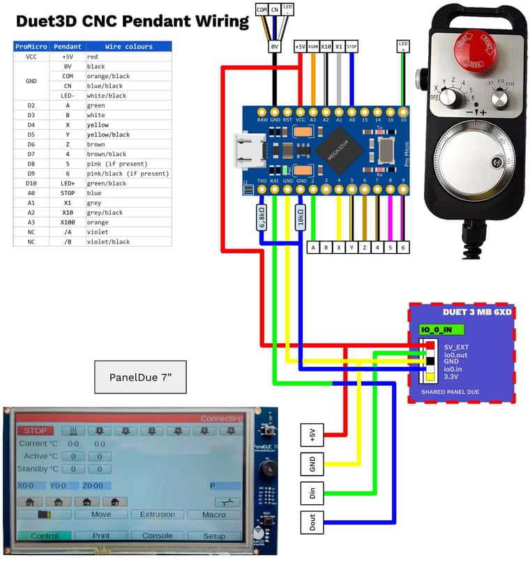
If there's no PanelDue, no wire needs to be connected between the Arduino RX and the Duet. As it says on the wiki:
If you do not intend to use a PanelDue at the same time as the pendant, it's best to leave the green wire of the 4-core cable (the one that would be connected to DOUT on the PanelDue) not connected to the Arduino RX0 pin, otherwise it might pick up noise.
Ian
Bed-slinger - Mini5+ WiFi/1LC | RRP Fisher v1 - D2 WiFi | Polargraph - D2 WiFi | TronXY X5S - 6HC/Roto | CNC router - 6HC | Tractus3D T1250 - D2 Eth
-
@droftarts
Thanks !
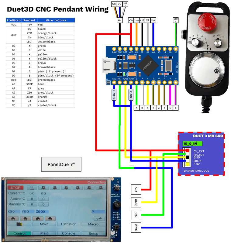
I've just updated the svg : https://drive.google.com/file/d/1mnaXqU4zVAt4ciulPTDM1ZS2i1TMj-y_/view?usp=sharingHere's the png :
-
@jeffouille I've updated the CNC Pendant wiki page, to include your wiring diagram (modified to show the connections for Duet 2 as well), the wiring tables from the Github page, and revised the text for clarity. Thanks for your help!
https://docs.duet3d.com/en/User_manual/Connecting_hardware/IO_CNC_PendantIan
-
 undefined Phaedrux referenced this topic