[3.5.2] Accelerometer not found
-
@bernardomattiucci What version of RRF were you running before updating? What accelerometer are you using? Please post your full config.g.
Ian
Bed-slinger - Mini5+ WiFi/1LC | RRP Fisher v1 - D2 WiFi | Polargraph - D2 WiFi | TronXY X5S - 6HC/Roto | CNC router - 6HC | Tractus3D T1250 - D2 Eth
-
RRF 3.4.6 with DWC 3.5.1
; Configuration file for Duet WiFi (firmware version 3.3) ; General preferences M575 P1 S1 B57600 ; enable support for PanelDue G90 ; send absolute coordinates... M83 ; ...but relative extruder moves G21 ; Work in millimetres M550 P"Quadra600" ; set printer name ; Network M552 S1 ; enable network M586 P0 S1 ; enable HTTP M586 P1 S0 ; disable FTP M586 P2 S0 ; disable Telnet ; Drives M569 P0 S1 ; X Axis - physical drive 0 goes forwards M569 P1 S1 ; Y Axis - physical drive 1 goes forwards M569 P3 S1 ; Extrusor - physical drive 3 goes forwards M569 P5 S0 ; Z1 Axis - physical drive 5 goes backwards M569 P6 S0 ; Z2 Axis - physical drive 6 goes backwards M569 P7 S0 ; Z3 Axis - physical drive 7 goes backwards M569 P8 S0 ; Z4 Axis - physical drive 8 goes backwards M584 X0 Y1 Z5:6:7:8 E3 ; set drive mapping M92 X80.00 Y80 Z800.00 E393.00 ; set steps per mm era 397 estrusore E3D HEMERA ;M92 X80 Y80 Z800 E197 ; estrusore MK8 M350 X128 Y128 Z128 E128 I1 ; configure microstepping with interpolation M566 X500 Y400 Z50 E600 ; set JERK - maximum instantaneous speed changes (mm/min) M203 X26000.00 Y26000.00 Z900.00 E2400.00 ; set maximum speeds (mm/min) M201 X2200.00 Y1600.00 Z100.00 E1000.00 ; set accelerations (mm/s^2) M906 X1900 Y1900 Z1800 E800 I30 ; set motor currents (mA) and motor idle factor in per cent M84 S30 ; Set idle timeout ; Axis Limits M208 S1 X-1 Y-8.5 Z-1 ; set axis minima M208 S0 X612 Y616.5 Z606 ; set axis maxima ; Endstops M574 X1 S1 P"xstop" ; configure active-high endstop for low end on X via pin xstop M574 Y1 S1 P"ystop" ; configure active-high endstop for low end on Y via pin ystop M574 Z1 S1 P"duex.e2stop+duex.e3stop+duex.e4stop+duex.e5stop" ; configure active-high endstop for low end on Z via pin duex.e2stop+duex.e3stop+duex.e4stop+duex.e5stop ; Z-Probe M558 P9 C"^zprobe.in" H5 F90 T7500 ;A10 S0.03 ; set Z probe type to bltouch and the dive height + speeds probe up to 5 times until 2 consecutive readings are within 0.005, if none average of 5M307 H3 A-1 C-1 D-1 ;M558 P0 M950 S0 C"duex.pwm5" ; create servo pin 0 for BLTouch G31 P25 X-35 Y0 Z2.7 ; setup BLTouch M557 X35:577 Y35:580 P21 ; define mesh grid M376 H1.1 ; Heaters ; piano di stampa ;M308 S0 P"bedtemp" Y"thermistor" T100000 B4092 ; configure sensor 0 as thermistor on pin bedtemp ;M950 H0 C"bedheat" T0 ; create bed heater output on bedheat and map it to sensor 0 ;M307 H0 R0.475 K0.642:0.000 D3.97 E1.35 S1.00 B1 ;M140 H0 ; map heated bed to heater 0 ;M143 H0 S120 ; set temperature limit for heater 0 to 120C ; estrusore M308 S1 P"e0temp" Y"thermistor" T100000 B4092 ; configure sensor 1 as thermistor on pin e0temp M950 H1 C"e0heat" T1 ; create nozzle heater output on e0heat and map it to sensor 1 M307 H1 R1.244 K0.203:0.000 D7.07 E1.35 S1.00 B0 V24.2 ; estrusore E3D HEMERA ;M307 H1 R2.070 K0.409:0.000 D6.16 E1.35 S1.00 B0 V24.2 ; estrusore MK8 M143 H1 S300 ; set temperature limit for heater 1 to 280C ; Fans ;Extruder Fan M950 F1 C"fan0" Q500 ; create fan 0 on pin fan0 and set its frequency M106 P1 S0 C"Extruder Fan" H1 T40 ; set fan 0 value. Thermostatic control is turned on ;Layer Fan M950 F0 C"duex.fan3" ; create fan layer on pin duex.fan3 and set its frequency M106 P0 S0 L90 C"Layer Fan" H-1 ; set fan 3 value. Thermostatic control is turned off ;Nozzle led M950 F2 C"duex.e2heat" ; Luci LED nozzle M106 P2 S0 L255 X255 C"Led" H1 T40 ; Tools M563 P0 D0 H1 F0 S"Hemera" ; define tool 0 E3D Hemera G10 P0 X0 Y0 Z0 ; set tool 0 axis offsets G10 P0 R0 S0 ; set initial tool 0 active and standby temperatures to 0C M572 D0 S0.09 ; Set or report extruder pressure advance ; Custom settings are not defined M204 P1000 T1400 ; Set printing and travel accelerations (mm/s^2) M669 K0 ; select Kinematics Y to react with X and Z ;M579 X1.0169 Y1.012 Z0.9704 ; Set Scale Cartesian axes ; Filament runout sensor M591 D0 P2 C"e0stop" S1 ; filament monitor connected to E0 endstop ; Emergency Stop M950 J1 C"!duex.e6stop" M581 P1 T0 C0 S0 ;Accelerometer M955 P0 C"spi.cs3+spi.cs4" I14 M593 P"zvdd" F18 S0.1 ; input shaping to cancel ringing ; Miscellaneous ;M911 S10 R11 P"M913 X0 Y0 G91 M83 G1 Z3 E-5 F1000" ; set voltage thresholds and actions to run on power loss T0 ; select first tool global Bed_layers_initial_number = 1 global Bed_layers_initial_temperature = 2 global Bed_layers_limit_number = 3 global Bed_layers_limit_lower_temperature = 4 global Bed_layers_limit_highest_temperature = 5 -
@bernardomattiucci Nothing much has changed with the accelerometer between 3.4.6 and 3.5.1, so I'm not sure why it would suddenly stop working. Did you follow the wiring as described here https://docs.duet3d.com/en/User_manual/Connecting_hardware/Sensors_Accelerometer#wiring
Again, what accelerometer are you using?
Do you have a PanelDue connected using both the 4-wire and ribbon cable? This has caused accelerometers not to work. If you have both connected, try disconnecting the ribbon cable.
Ian
Bed-slinger - Mini5+ WiFi/1LC | RRP Fisher v1 - D2 WiFi | Polargraph - D2 WiFi | TronXY X5S - 6HC/Roto | CNC router - 6HC | Tractus3D T1250 - D2 Eth
-
@droftarts In fact, I'm double-checking because something doesn't feel right about the connections. I've been redoing them several times in the last few months and I may have made some mistakes.
-
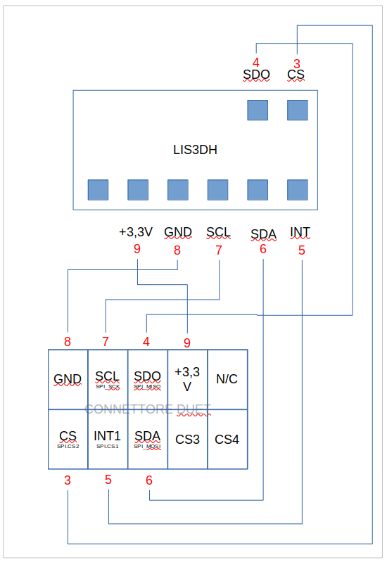
this is my current scheme, but the accelerometer is still not seen.
To premise that I have a Duex5 board connected, so I don't know if it can affect it.
Before the update, however, I was not getting any errors. This is 100% certain.
I had wires 3 and 4 (red colored numbers) connected to CS3 and CS4 and it was working.
-
@bernardomattiucci From your diagram, you have CS on the accelerometer connected to spi.CS2 on the TEMP_DB socket, and INT connected to spi.CS1. You don't have any temperature boards configured in config.g; is the accelerometer plugged in on top of one? Try:
M955 P0 C"spi.cs2+spi.cs1" I14How is your PanelDue connected? If you're using the 4-wire connection and ribbon cable, disconnect the ribbon cable. See https://forum.duet3d.com/post/338515
Ian
Bed-slinger - Mini5+ WiFi/1LC | RRP Fisher v1 - D2 WiFi | Polargraph - D2 WiFi | TronXY X5S - 6HC/Roto | CNC router - 6HC | Tractus3D T1250 - D2 Eth
-
@droftarts the problem is in the cable.
I just made one 30 cm long and it is seen regularly.
the problem is that my electronics are separate from the printer and the distance is considerable. It needs a well-shielded cable, which I don't have at the moment, so I had made one using a flat-cable, but evidently it is not shielded well. I will do more testing tomorrow and try to solve it!Thanks
-
One of the terminals on the Duet side connector, was not perfect and I had to redo it, changing the connector as well.
Now it works, so I would say this problem is solved.
Occasionally, during the "record motion profile" operation, it gives me some problems. I don't know if it depends, as I read, on the SD-Card or the cable that is not perfect. Patience!
-
@bernardomattiucci Great, glad you have resolved this. Some users on the forum have suggested using USB3 cable for longer runs, which are generally high quality and shielded. For a guide to wiring USB3 cables, see. https://teamgloomy.github.io/fly_e3_pro_v3_accelerometer.html
Ian
Bed-slinger - Mini5+ WiFi/1LC | RRP Fisher v1 - D2 WiFi | Polargraph - D2 WiFi | TronXY X5S - 6HC/Roto | CNC router - 6HC | Tractus3D T1250 - D2 Eth
-
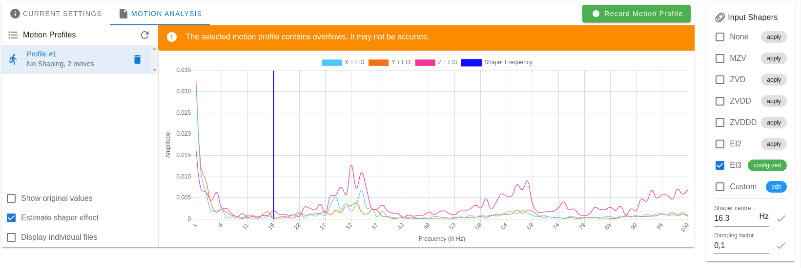
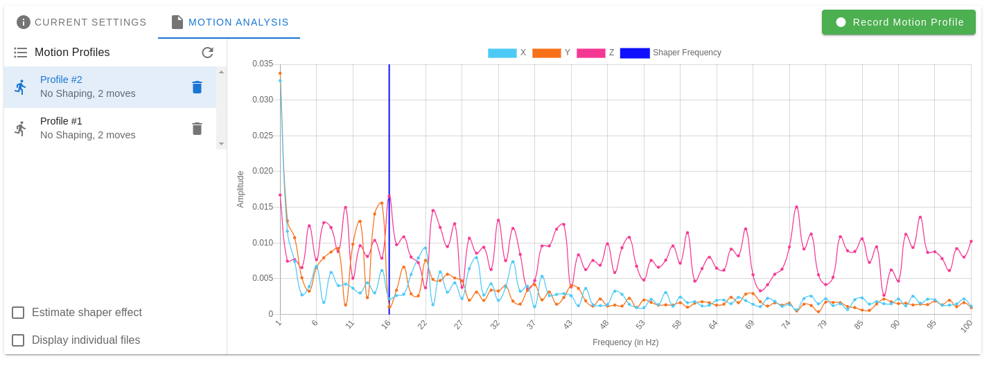
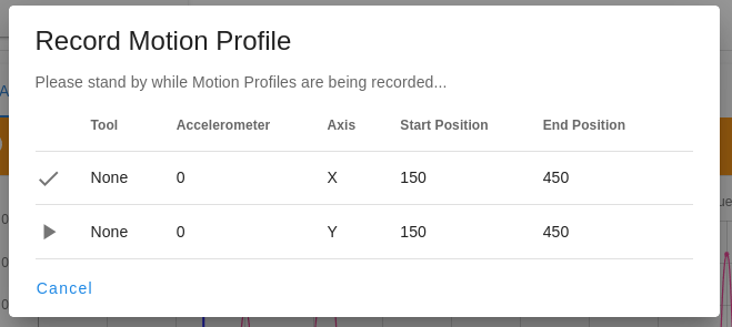
@droftarts Using the "input shaping" plugin with the "record motion profile" button, the result is always the same: "The selected motion profile contains overflows. It may not be accurate."
Is there any way to solve the problem without necessarily replacing the SD-CARD?
-
@bernardomattiucci Ideally, a faster SD card. Otherwise, reduce the number of samples you are collecting. You can do this by either reducing the length of the move in the input shaper plugin (ideally the move only need to get to the maximum speed and back to stopped) or by reducing the frequency of sampling. I think there's no option to change this in the plugin, so you would need to capture the data with manual commands.
Ian
Bed-slinger - Mini5+ WiFi/1LC | RRP Fisher v1 - D2 WiFi | Polargraph - D2 WiFi | TronXY X5S - 6HC/Roto | CNC router - 6HC | Tractus3D T1250 - D2 Eth
-
The first half of the cable I replaced with a USB-3.
Tomorrow I will prepare the other half and test it.... if it gives me any improvement in results I will install it, otherwise I will leave the current one.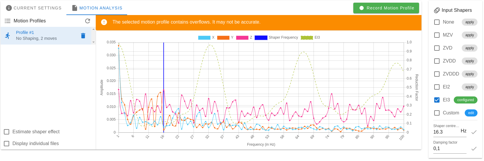
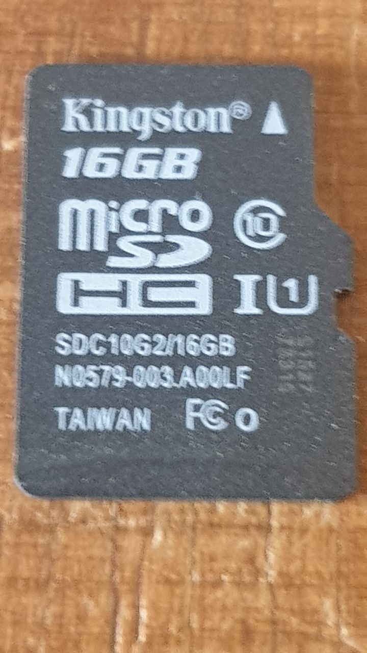
Wanting to buy a new SDCard, do you recommend BRAND and MODEL to get online?
I currently have this:
And before that there was this one:
-
@bernardomattiucci The 16GB class 10 card should be okay. Kingston, SanDisk and other name brands are usually okay.
Ian
Bed-slinger - Mini5+ WiFi/1LC | RRP Fisher v1 - D2 WiFi | Polargraph - D2 WiFi | TronXY X5S - 6HC/Roto | CNC router - 6HC | Tractus3D T1250 - D2 Eth
-
@droftarts I will test with the other half of the cable. But to solve the problem I have to figure out what it is and why that kind of "error" is generated. At the moment I have no idea what it is!
-
I mounted the second section of usb3 cable and after a few unsuccessful attempts, it recorded the track without the error.
I'll do some more tests.In the meantime, thank you
-
Occasionally the plugin seems to get stuck. I don't know if it depends on something in my installation or if it is a bug in the plugin, because the data all seems to be there. Even the overflows!
-
I have performed other tests and the result is still the same. Until a few firmware versions ago, I think before 3.2 but I don't remember well, when input shaping was an external plugin, the error "The selected motion profile contains overflows" never appeared. Then with an update it started to appear.
I rewired and not much has changed (i.e... now at least it works, albeit with data overflow).
Question: does the presence of this error, in any way affect the proper functioning of input shaping?
Thanks