Duet Main board integration with TIG WELDER
-
Re: Duet 6 HC and 3HC Board Not able to Integrate with WELDER
This message is drafted in relation to a previous post.
Have used a 6HC mainboard and 3HC mainboard for operating a welding machine with multiple motion system.
Using a daemon.g file to change the feed rate of the wire feeder motor.
A simple 5V relay is being used for switching the WELD MACHINE ON/OFF.
- OUT 9 IO Pin is connected to the relay and is used to switch the WELD MACHINE ON and OFF through a macro file.
Macro file for the same is as follows
; Weld Torch ON
M42 P3 S0 ; turns on the relay
;set WeldTorchState to ON
global.WeldTorchState = 1
; Weld Torch OFF
M42 P3 S1 ; turns off the relay
; set WeldTorchState to OFF
global.WeldTorchState = 0
WELDMACHINE : CITOTIG 2200 FORCE
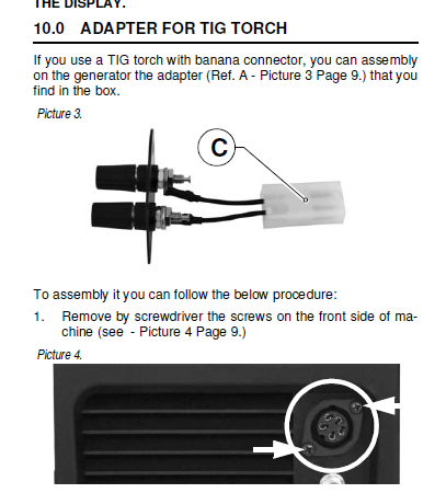
WELD MACHINE CONNECTION TO DUET MAINBOARD 6HC Through connector as shown below via 5V Relay

During the operation of the welder an arc is established but the axis stops moving. Suspecting some kind of EMF interference caused by the weld circuit.
- OUT 9 IO Pin is connected to the relay and is used to switch the WELD MACHINE ON and OFF through a macro file.
-
@SANJR Your macro switches the relais on/off in a very short time. Too short for the relais?
If the welder needs a short pulse to switch on, you should add a G4 (dwell time) in the macro with the appropriate pulse-length. -
Thanks
Arc was established, torch that was mounted on the X axis stopped moving.
Error message displayed as EXPANSION BOARD ERROR
The X & Y Axis are mounted to the expansion board.
So for a quick check when the X and Z axis limit switch sensors are removed. No such error was seen
-
@SANJR said in Duet Main board integration with TIG WELDER:
So for a quick check when the X and Z axis limit switch sensors are removed. No such error was seen
If you happen to have optical endstops, they might have been disturbed by the arc?
-
@SANJR if it works when you disconnect the X and Y limit switch sensors from the Duet, then one of the following may help:
- grounding the metalwork of the machine (if it isn't already) and connecting Duet VIN negative to that ground;
- using shielded cable t connect the limit switches.
-
THANKS
The first Option ¨grounding the metalwork of the machine (if it isn't already) and connecting Duet VIN negative to that ground;¨
- Means the frame of the machine to be connected to the by a wire and let it down to the floor of the lab. Am i correct?
- And if yes what gauge of the wire would suit it any suggestions would be helpful on this.....
The second option ¨using shielded cable t connect the limit switches¨
- I am searching for a place to buy these kind of cables any link to purchase would be much appreciated..
Finally I was thinking to use a more robust limit switch sensors that is able to withstand these kind WELD EMF interference. Any suggestions on these would be most welcome......
-
@SANJR said in Duet Main board integration with TIG WELDER:
Means the frame of the machine to be connected to the by a wire and let it down to the floor of the lab. Am i correct?
No, connect it to the ground conductor in the mains cable. From the point of view of avoiding the interference that may be causing the problem, the gauge doesn't matter. From a safety perspective, the gauge should be similar to the gauge of the mains supply cable.
I am searching for a place to buy these kind of cables any link to purchase would be much appreciated.
Mono shielded audio cable would be suitable. Here's an example: https://www.amazon.co.uk/ICOBES-Channel-Electronic-Shielding-Shielded/dp/B0C7QC1QGQ. The gauge isn't critical but 20 or 22awg will be easier to crimp than 24awg. Connect the shieled to the ground pin of the Duet endstop connector and the centre conductor to the STP or IO_IN pin.
-
Thanks dc42
-
Greetings dc42
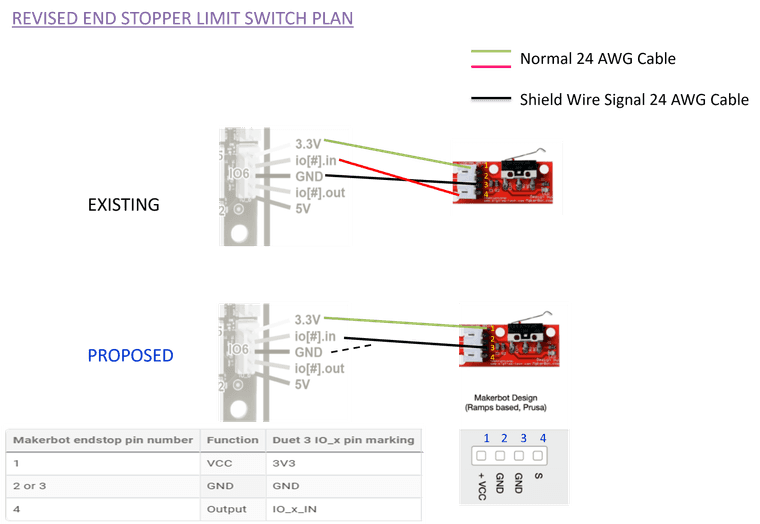
Herewith attached REVISED END STOPPER WIRING LAYOUT.
In the existing plan, the io.in pin of duet is connected to the S pin of the end stopper (PIN:4). In the REVISED Layout this S pin (PIN 4 of end stopper) left blank and from the shielded Wire Signal cable, the shield cable is connected to GND (DUET) and central conductor is connected to io.in pin (DUET).
Is this layout correct. Requesting for any corrections or suggestions plz

-
@SANJR I was assuming you were using 2 pin endstops. Yours are 3 pin so the cable you need is 2 core + shield. Your "Existing" diagram is correct i.e. use the shield as ground and the 2 cores to carry the 3.3V and IO_IN signals.
-
Thanks dc42
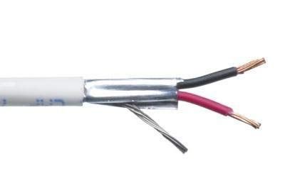
Below is the picture of 22 AWG 2 Core + Shield cable from Amazon. Previously used 24 AWG, hope this 22 AWG wouldnt be a issue.

The updated REVISED SHIELD Cable for reference. Is it okay?
GND (Duet) -> Pin 3 (Endstop)
3.3V (Duet) -> Pin (Endstop)
io.in (Duet) -> Pin4 (Endstop)