Duet3D Logo Duet3D
    • Tags
    • Documentation
    • Order
    • Register
    • Login

    Duet3 Mini5+ FAN pin behavior at power lost

    Scheduled Pinned Locked Moved
    Laser Cutters
    3
    12
    469
    Loading More Posts
    • Oldest to Newest
    • Newest to Oldest
    • Most Votes
    Reply
    • Reply as topic
    Log in to reply
    This topic has been deleted. Only users with topic management privileges can see it.
    • T3P3Tonyundefined
      T3P3Tony administrators @titusou
      last edited by

      @titusou you can add an external pulldown resistor of say (4k7) to the pin.

      www.duet3d.com

      titusouundefined 1 Reply Last reply Reply Quote 0
      • titusouundefined
        titusou @T3P3Tony
        last edited by

        @T3P3Tony
        You mean in series between Duet and relay board?

        T3P3Tonyundefined 1 Reply Last reply Reply Quote 0
        • T3P3Tonyundefined
          T3P3Tony administrators @titusou
          last edited by

          @titusou no between the pin and ground.

          www.duet3d.com

          titusouundefined 1 Reply Last reply Reply Quote 0
          • titusouundefined
            titusou @T3P3Tony
            last edited by

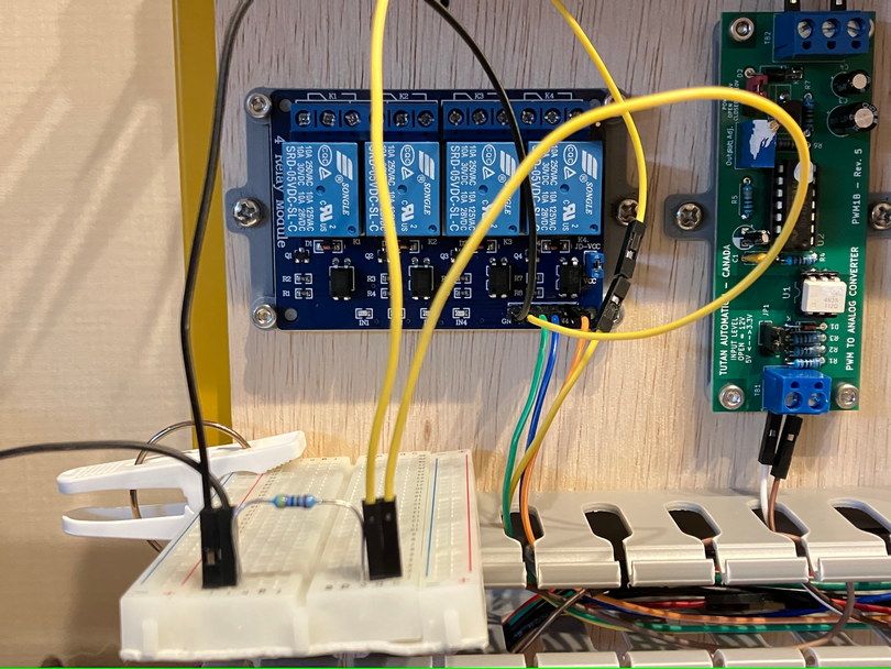
            @T3P3Tony I managed to get this work by...

            [PANEL DUE 5V_EXT] === Relay board VCC
            [PANEL DUE 5V_EXT] === 4.7K Ohm === [24V PSU -V]
            5v vcc pulldown.jpg

            If I do...
            [out3-] === Relay board [IN1]
            [out3-] === 4.7K Ohm === [24V PSU -V]
            The relay will enable when powerup, and remain on when power lost for a long time (probably until PSU completely dry)

            Did I do something odd?

            Thanks in advance!

            T3P3Tonyundefined 1 Reply Last reply Reply Quote 0
            • T3P3Tonyundefined
              T3P3Tony administrators @titusou
              last edited by

              @titusou said in Duet3 Mini5+ FAN pin behavior at power lost:

              [PANEL DUE 5V_EXT] === 4.7K Ohm === [24V PSU -V]

              interesting so you are draining the capacitance on the 5V supply via that resistor.
              Presumably the relay board V- is connected to proper ground?

              www.duet3d.com

              titusouundefined 1 Reply Last reply Reply Quote 0
              • titusouundefined
                titusou @T3P3Tony
                last edited by

                @T3P3Tony I'm currently have 5V PSU connected as isolated supply to the relay coil
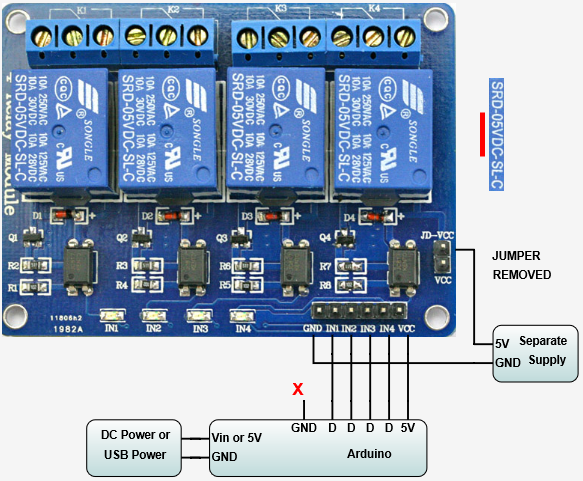
                efdb488f-9a61-4359-bfda-8bac6655d6cf-image.png

                231ebf75-0ca1-4166-b55c-4d231cb4b213-image.png

                So on the signal side there is really no GND.

                Is this going to cause some odd problem? Draining the board instead of pulldown signal?

                T3P3Tonyundefined 1 Reply Last reply Reply Quote 0
                • T3P3Tonyundefined
                  T3P3Tony administrators @titusou
                  last edited by

                  @titusou ok connect the grounds together otherwise you will have issues with stuff loating to different levels - as you are seeing.

                  www.duet3d.com

                  titusouundefined 1 Reply Last reply Reply Quote 0
                  • titusouundefined
                    titusou @T3P3Tony
                    last edited by titusou

                    @T3P3Tony Still acting odd...

                    I now have...

                    No external 5V PSU, all power by Duet's 5V.
                    Duet [PANEL DUE 5V_EXT] === Relay board [VCC], which jumper connect to [JD-VCC] to power coil
                    Duet [GND] === 24V PSU [-V] === Relay [GND]
                    Duet [out3-] === Relay board [IN1]
                    Duet [out3-] === 4.7K Ohm === 24V PSU [-V]

                    And relay enabled as soon as power on.

                    bd4db0bc-d5bb-4aac-a69f-7f385a70f332-image.png

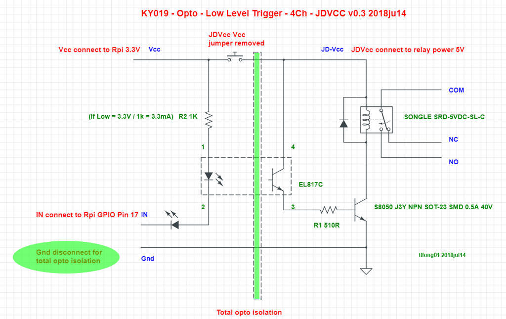
                    I check the relay board's schematic, and I think it's neg-side-controlled. So having pull-down on the [IN1] actually ground the [IN1] and cause it enable instantly at powerup.

                    So if that the case, having pull-down on the [VCC] is actually kind correct?

                    infiniteloopundefined 1 Reply Last reply Reply Quote 0
                    • infiniteloopundefined
                      infiniteloop @titusou
                      last edited by

                      @titusou
                      Referring to the KY019 schematics and the image above, you need to separate the logic level (3.3V) from both the input voltage the relay requires (5.0V) and the relays-controlled voltage (24.0V). With the JD-Vcc jumper in place (as spotted in the photo), the logic level requires 5.0V, which will not work, as the Duet-I/O uses 3.3V instead.

                      Remove the jumper JD-Vcc, feed 3.3V from the Duet into Vcc (labelled ”Vcc connect to Rai 3.3V”), feed 5.0V into JD-Vcc (labelled ”JDVcc connect to relay power 5V”). Possibly, you can forget about the pull-down resistor.

                      Oh, and don’t waste any further thought on whether or not to connect the V- of your PSUs: They need a common GND.

                      titusouundefined 1 Reply Last reply Reply Quote 1
                      • titusouundefined
                        titusou @infiniteloop
                        last edited by

                        @infiniteloop I got it works as you described. Thank you!!!

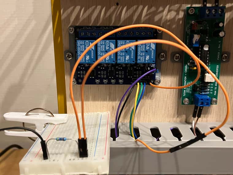
                        Some detail for future reference.

                        Duet [PANEL DUE 5V_EXT] ==(orange)== Relay [JD-VCC]
                        Duet [PANEL DUE 3.3V_EXT] ==(green)== Relay [VCC]
                        Duet [PANEL DUE GND] ==(black)== Relay [GND]
                        Duet [out3-] ==(yellow)== Relay [IN1]
                        Duet [out4-] ==(blue)== Relay [IN2]
                        Duet [out5-] ==(brown)== Relay [IN3]
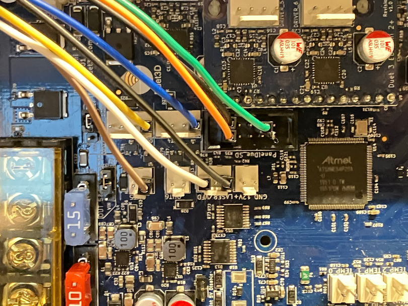
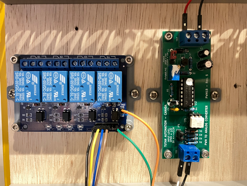
                        6673708b-eca8-40a8-8cd6-cf670a5a3606-image.png

                        83db91cc-387c-4398-8765-8e66b75b386f-image.png

                        config.g

                        ; Laser mode
                        M452 C"out6" R255 F200 ; Enable Laser mode, on out6, with max intensity being 255, and a PWM frequency of 200
                         
                        ; FAN-as-IO setup
                        M950 P0 C"out3" ; Red Laser
                        M950 P1 C"out4" ; Laser Enable
                        M950 P2 C"out5" ; placeholder
                        

                        No strange behavior during power on nor power lost. Everything looks good.

                        Note: the board next to relay is isolated PWN to 0-10V converter, in case someone wondering.

                        1 Reply Last reply Reply Quote 1
                        • First post
                          Last post
                        Unless otherwise noted, all forum content is licensed under CC-BY-SA