My Second build (in progress)
-
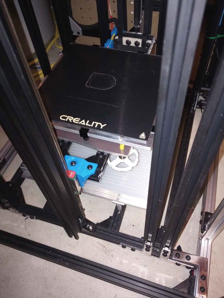
z axis belt have been put in , and the pulley ratio are doing their job well , bed is not dropping free working as intended . just waiting for the expansion board showing up in the mail to finish wiring , and organizing the last few wiring . with a bit of luck i might be able to test print this monster next week-end , still need to enclosed this things but it not my priority right now that for a later stage
-
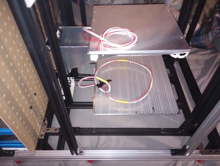
got the lED light and heated bed and heated chamber heater plugged
-
Bed-slinger - Mini5+ WiFi/1LC | RRP Fisher v1 - D2 WiFi | Polargraph - D2 WiFi | TronXY X5S - 6HC/Roto | CNC router - 6HC | Tractus3D T1250 - D2 Eth
-
@droftarts danm autocorrect lol

-
So got the expansion board up and running ,
Just need to work out a few sensor and the config and then i can put the xy axis belt on and fill up that water loop hopefully this weekend

-
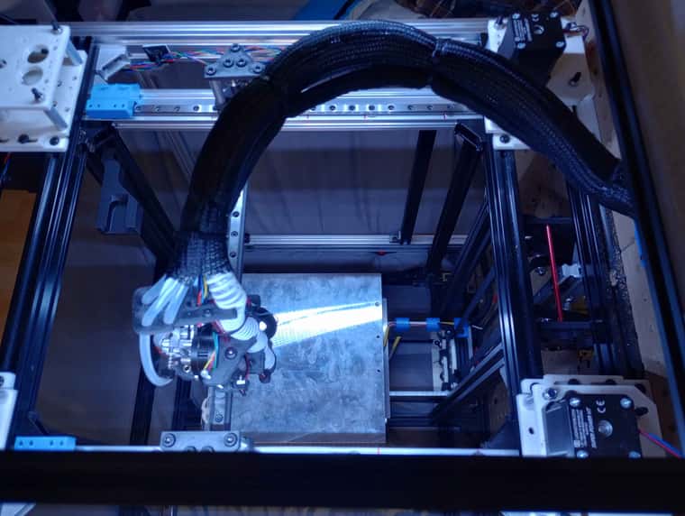
wiring is all done , basically only things left is to go throw the config and make sure axis and limit switch are good , need to replace some of the 3d printed gantry to aluminum , added an extra thermistor that will monitor temp of the gantry between both watercooled hotend and extruder . tested the cpap fan and it work even at 5% and it feel stronger than most fan ive tried before at that level , cant wait to test that baby at 100% lol were we come with speed run benchy lol

just need to dremel it a bit to get it closer of the 3d printed part and clean it a bit , might be a bit crude but him not worried about that lol


-
Had to redesign some part , there was a few issue but i might have this thing going today ! Reprinted a few part overnights , and hopefully they fix the problem then I only need to fill up the water loop .

-

-
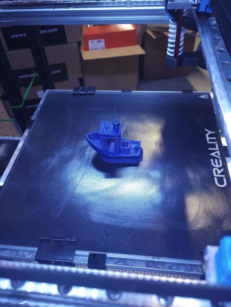
So now I need to calibrate things a bit more but I ended up doing it quick I wanted to test print lol
So far it seem the single 2020 were the z axis rail is, is not stiff enough and make the bed shake a bit , so I will need to had Some reinforcement to stiffen that . Need to work on my klicky dock as well . test printed with some old PLA that i had laying around ,
current setting in config is :
; Axes
M584 X0.0:0.1:0.2 Y0.4:0.5:0.3 Z1.1:1.2 ; set axis mapping
M350 X16 Y16 Z16 I1 ; configure microstepping with interpolation
M906 X2400 Y2400 Z1200 ; set axis driver currents
M92 X80 Y80 Z2560 ; configure steps per mm
M208 X10:205 Y-40:200 Z0:300 ; set minimum and maximum axis limits
M566 X900 Y900 Z100 ; set maximum instantaneous speed changes (mm/min)
M203 X90000 Y90000 Z500 ; set maximum speeds (mm/min)
M201 X20000 Y20000 Z500 ; set accelerations (mm/s^2)him curious to see how far i can push this machine once i fix the last few things
-
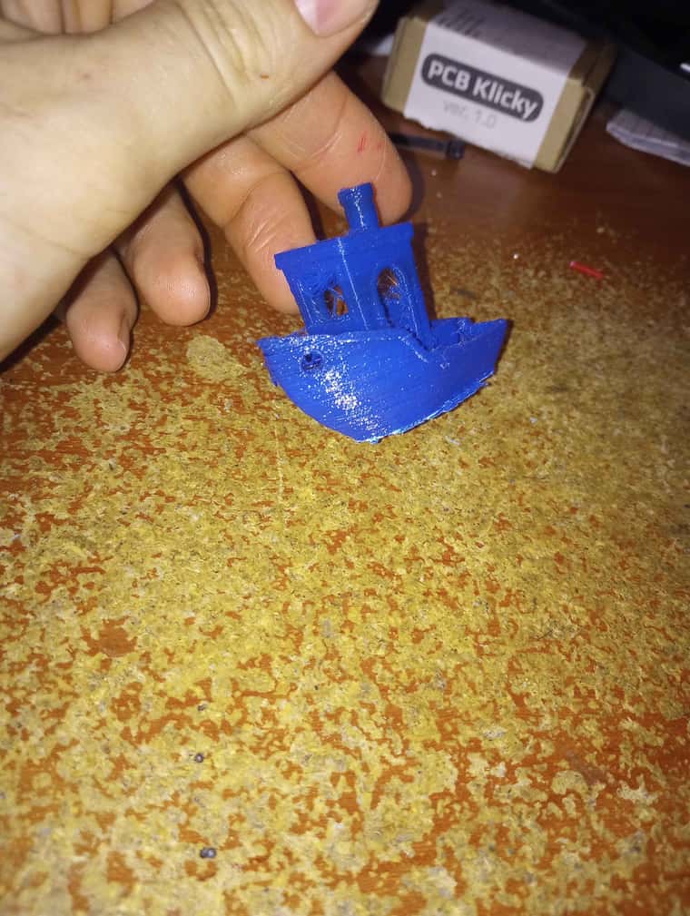
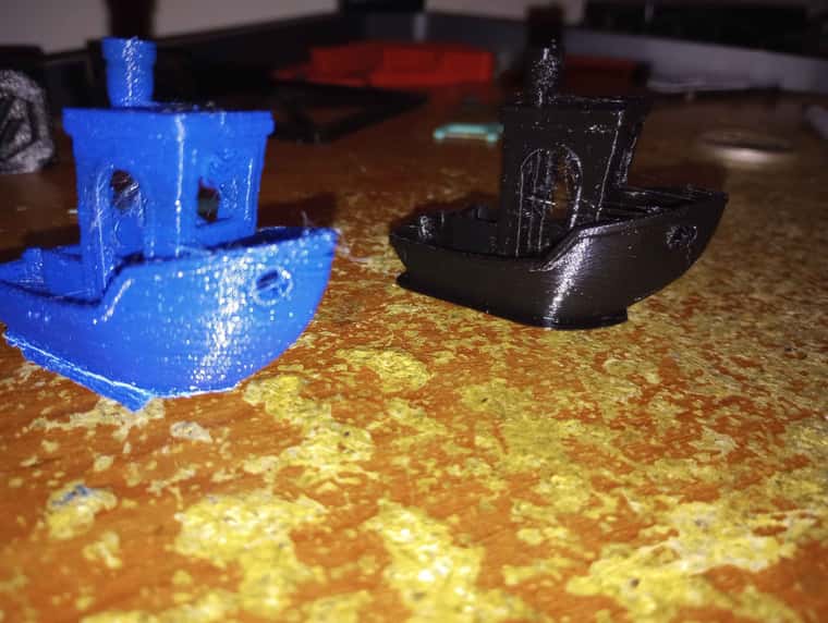
so a bit rough looking and lots of stringing from the old pla but not the worst benchy ive ever seen since it on an untuned machine , lots of stringing lol
-
Did some further tuning , extruder is nearly fully dial , skew compensation should be bang on , z axis step seem fine , just need to reinforce the z axis and we should all be set for more printing test .
-
Got the accelerometer working tonight and I it seem zvddd at 40-42hz was the flatest curve like.
Tomorrow I can hopefully fix the print bed shaking and keep going on those calibration and push the speed to see how far it can go -
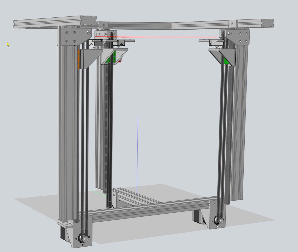
Well adding up reinforcement on the z axis didn't seem to have fixed my issue , i think i would just have to double the linear rail and block on it , but i had some old mgn15 rail laying around and tested something , so i decided to put that rail at the front of the platform , it look at bit goody but so far it seem to have completely eliminated any wobbling of the print bed . platform goes up and down without any problem , so i think him gonna test this a bit more and see how to it goes . before i order any more rail for this
-
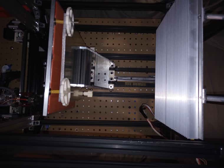
I had my bed being lifted at three points, so as to allow auto leveling.
I used steppers with integral planetary gearboxes. He are most of the parts related to the Z axis. It is quite simple, to my way of thinking.
Regards, Frederick
-
@fcwilt yea , my goal was to keep it simple with only one axis to power the bed , I always run a bed mesh before print so bed leveling doesn't need to be 100% perfect , him just testing things out .
-
@Dad003 said in My Second build (in progress):
@fcwilt yea , my goal was to keep it simple with only one axis to power the bed , I always run a bed mesh before print so bed leveling doesn't need to be 100% perfect , him just testing things out .
True but the flatter and more level the bed is, the less work mesh compensation needs to do.
And as you can see with planetary steppers you only need the toothed pulley on the stepper and the toothed idler at the other end. Doesn't get much simpler than that.
And watching a bed auto level is kind of fun.

Frederick
Printers: a E3D MS/TC setup and a RatRig Hybrid. Using Duet 3 hardware running 3.4.6
-
well i ve done some testing and him close to figure out the acceleration and jerk this things like , tried a 150x150 square with only 2 layer for wall , and was able to get the movement speed up to 1200mm/Sec without skipping but it was at the edge of the acceleration . but 900-1000mm/sec no issue
-
@fcwilt And if you do it right, there's no need for mesh compensation or auto tramming.
I use a single NEMA 23 stepper with a 30:1 worm drive gearbox to lift the bed on two linear guides in my printer. It has an 8 mm thick cast tooling plate bed on a kinematic mount. There's no autotramming or mesh compensation. The last time I trammed the bed was at least 2 years ago, and it took less than a minute. It just works every time I turn it on. The bed doesn't move when power is cut, so theoretically I can resume printing after a blackout, though I've never tried.
-
Everything you say is mostly true.
Cast tooling plate is typically flat within 0.015" or 0.381 mm.
The worst case means the plate may be "out of flat" by nearly 4 layers when printing at 0.1 mm layers.
I have my machinist verify the flatness after creating a bed plate.
As to tramming I rather enjoy watching a triple Z setup level the bed.
Frederick
-
@fcwilt said in My Second build (in progress):
The flatness spec is based on an entire sheet (4'x12' or so) of tooling plate. Typical flatness over a smaller piece is usually much better. In my printer, I would guess the varying thickness of the PEI and adhesive sheet under it are likely to contribute more to the unflatness than the plate itself. I have never tried to print a 100um first layer- I'm not sure why that would be needed - but I do print with 200 um first layers once in a while without any trouble.
The purpose of tramming/mesh compensation is to get the first layer to stick for the duration of the print, not to get a flat bottom on the print. If you move the Z axis up and down to compensate for bed unflatness or tramming error, you're not going to have a flat bottom on the print - it's going to be the shape of the bed, whatever that is. I can't imagine any application for a plastic 3D print where the flatness of its bottom, beyond what comes off the bed, would be critical to the function or appearance of the print. If flatness down to micron level is needed, a 3D printer is the wrong way to make the part in the first place.
Auto tramming and multiple screws/motors to lift the bed are a chicken and egg sort of thing. A lot of people think they want auto tramming so they use multiple screws/motors to lift the bed. But if you use multiple screws/motors, you have to use auto tramming because the bed is going to tilt every time you cycle power to the printer. I think what people really want is a reliable printer that they don't have to mess around with, but youtube videos showing corners of beds going up and down have made them think that auto tramming is the only way to achieve that.
If you use a single motor to lift the bed, regardless of the number of screws or belts, the bed won't tilt when you cycle power. If the bed plate is on a stable mount, it won't require tramming every time you print. You won't need bed sensors, multiple motors, drivers, and cables. And you'll never experience the joy of troubleshooting it when it fails.
I enjoy starting prints and not waiting for the machine to tram itself. I also enjoy not having to worry about whether the print is going to stick or whether I'll be able to to print at all if auto tramming fails. There's less to go wrong with a flat bed plate on a stable mount that doesn't require tramming before every print.