z-probe ADC voltage
-
I'd like to test underbed FSR's on my delta.
To tune my circuit externally, i need to know the voltage range of the z-probe ADC input.
Which voltages are needed to display the values 0 and 1000 in DWC? -
@cosmowave Usually, 0 to 3.3V. What board is this? If it's Duet 2, the maximum voltage depends on the board revision. The Z_PROBE_IN pin of the Z_PROBE connector is 30V-tolerant in revision 1.04 and later, but only 3.3V-tolerant in revision 1.03 boards and earlier. For Duet 3, all inputs are 30V-tolerant.
Ian
Bed-slinger - Mini5+ WiFi/1LC | RRP Fisher v1 - D2 WiFi | Polargraph - D2 WiFi | TronXY X5S - 6HC/Roto | CNC router - 6HC | Tractus3D T1250 - D2 Eth
-
@droftarts Thanks for your answer. It's a Duet2... i think at least 1.04. Have to check that.
Is it correct, that also on the 30V tolerant boards, the ADC Input reads voltages between 0V to 3.3V as 0 to 1000 (in DWC)? -
@cosmowave said in z-probe ADC voltage:
Is it correct, that also on the 30V tolerant boards, the ADC Input reads voltages between 0V to 3.3V as 0 to 1000 (in DWC)?
I believe so, yes. You'll need to use an analog probe type. See https://docs.duet3d.com/en/User_manual/Connecting_hardware/Z_probe_connecting
Small FSR section here: https://docs.duet3d.com/en/User_manual/Connecting_hardware/Z_probe_connecting#force-sensitive-resistorsIan
Bed-slinger - Mini5+ WiFi/1LC | RRP Fisher v1 - D2 WiFi | Polargraph - D2 WiFi | TronXY X5S - 6HC/Roto | CNC router - 6HC | Tractus3D T1250 - D2 Eth
-
Tapping into this conversation; We made a loadcell amplifier board with the INA818 op-amp to boost the loadcell signal and we got a range of 80mV to 2.3V output, which we now wired to the temp2 input of our roto toolboard.
It successfully works when we configure it as a linear-analog sensor with M308, after which it shows as a temperature readout.
is there a way to convert this software-wise to a probing input?? I cannot figure out how to set P1 or P3 type from a thermistor input pin
-
@SanderLPFRG If it's capable of outputting near-full range 0-3.3V, connect it to a normal IO pin, not a temperature pin. The temperature pins have a voltage divider circuit, to better measure the changing resistance of a temperature sensor. Configure with M558, not M308.
I'd be interested in seeing the amplifier circuit; it would be good to have load cell support in RRF too.
Ian
Bed-slinger - Mini5+ WiFi/1LC | RRP Fisher v1 - D2 WiFi | Polargraph - D2 WiFi | TronXY X5S - 6HC/Roto | CNC router - 6HC | Tractus3D T1250 - D2 Eth
-
Thanks for the quick reply.
The loadcell circuit is now implemented to a custom Devboard we made, and therefore hardwired to a "Thermistor input". (based of of this previous topic; https://forum.duet3d.com/post/262561) We will see if we can rewire it to an IO input.
Can we then configure the P1 analog sensor from an expansion board??
As for the files; sure, we got a lot of help from the community so it would be nice to give something back. I cannot give the schematic tho, since that is still in development.
Basically, we self-developed the wheatstone-bridge load cell sensor with the 4-wire pinout (EXC+, EXC-, Sig- and Sig+). Then we wired these to an INA818 op-amp to amplify the signal significantly and used some diodes to limit the output voltage to 80mV and 1.92V to protect the ADC input on the chip. Amplification is set with a resistor -
@SanderLPFRG I'm not aware of any limitation on the pin you can define with M558, so if the load cell amplifier is outputting a signal that can be interpreted by a temperature pin, I'd think it would work. Does something like this work?
M558 P1 C"121.temp2" H5 F120 T3000In DWC, check the ZProbe range when there is load on the load cell.
Ian
-
@SanderLPFRG @jay_s_uk has just reminded me that probes connected to Duet 3 expansion boards are limited to types 8 and 9. Firmware 3.5 also supports type 11 (SZP).
Ian
Bed-slinger - Mini5+ WiFi/1LC | RRP Fisher v1 - D2 WiFi | Polargraph - D2 WiFi | TronXY X5S - 6HC/Roto | CNC router - 6HC | Tractus3D T1250 - D2 Eth
-
@droftarts Hi,
Get it, so I can only connect a digital sensor to the expansion boards??
May I ask why this limitation is in place? and is there a way to hack myself around it in firmware? Like can I trick the firmware into thinking there is a SZP connected? that seems to put out analog signal as well.
-
@SanderLPFRG It's listed as 'technically possible' in the restrictions section, here: https://docs.duet3d.com/User_manual/RepRapFirmware/CAN_limitations#semi-permanent-limitations. I'm not a programmer, so I don't know what firmware changes would be needed. One for @dc42.
I think the main reason for no analog support on toolboards is slow update. A digital signal is faster than an analog signal to compute and send over CAN, particularly when you need to control motors to stop eg when homing axes. An FSR board that outputs a digital signal might be an easier option, eg https://github.com/JohnSL/FSR_Endstop, then you can use probe type 8.
As far as I'm aware, the SZP sends a digital signal. The MCU on the board is dedicated to converting the eddy current reading, so there is less overhead.
Ian
-
@droftarts said in z-probe ADC voltage:
I'd be interested in seeing the amplifier circuit; it would be good to have load cell support in RRF too.
As info:
I was working on a amplifier for my FSR's in the last days. If you are interesed, here's my quick and dirty scheme of the circuit.
The amplifier is built with a double op amp OPA2340 and is able to adjust the offset and gain separately.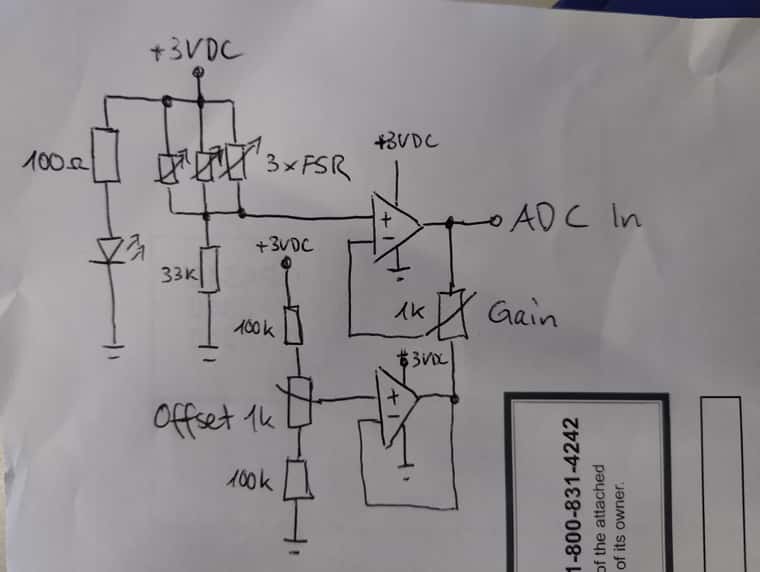
It is not yet perfect, but it works good in my "test environment". I will add at least a low pass filter somewhere in the signal line to filter out possible stepper EMF's. But i have to thinking about where and how...
EDIT: the 100 ohm resistor and the LED is not needed, it shows only if the circuit is powered...