Correct way to set Steps Per mm for X and Y
-
Everything is working fine except Some backlash
i am having some backlash issues on my OpenPnP with a Duet3 6XD Controller and i am trying to verify that my " Steps Per mm" are correctly calibrated on Duet3 6XD with M92 command and calculated correctly
The X & Y axes use an External driver HSS86 with 86HSE8N-BC38 Closed loop NEMA 34 motor .
The Microstepping is configured on the External Driver at 3200 pulses/rev as below using Dip Switches on the external driver
SW1=ON, SW2=ON, SW3=OFF, SW4=OFF, SW5=ON, SW6=ONHere is what i have in my config.h for the M92 command.
M584 X0.0 Y0.1 Z1.0 U1.1 V1.2 W2.0 A2.1 B2.2 C3.0 D3.1 'G3.2  S0 ;  LIN R0 = LINEAR, R1 = ROTATION


M350 Z16 U16 V16 W16 A16 B16 C16 D16 'G16 I1         ; configure microstepping with interpolation. Irrelevant for external drives X, Y,  (X & Y = Dip Switches 3200= SW1=ON,SW2=ON,SW3=OFF,SW4=OFF,SW5=ON,SW6=ON)
M92 X64.00 Y64.00 Z20.00 U20.00 V20.00 W8.888 A8.888 B8.888 C8.888 D8.888 'G8.888                  ; set steps per mm, 50mm/rev. (X & Y = Currently 3200 pulse/rev / 50 revs = 64 Steps)
M566 X900.0 Y900.0 Z900.0 U900.0 V900.0 W7200.0 A7200.0 B7200.0 C7200.0 D7200.0 'G7200.0  P1       ; set maximum instantaneous speed changes (mm/min) and use Jerk policy 1
M203 X126000.00 Y126000.00 Z24000.00 U24000.00 V24000.00 W3600000.00 A3600000.00 B3600000.00 C3600000.00 D3600000.00 'G3600000.00    ; set maximum speeds/feedrate (mm/min)
M201 X5000.00 Y5000.00 Z2000.00 U2000.00 V2000.00 W180000.00 A180000.00 B180000.00 C180000.00 D180000.00 'G180000.00                  ; set accelerations (mm/s^2)
M906 Z1360.0 U1360.0 V1360.0 W560.0 A560.0 B560.0  C560.0 D560.0 'G560.0  I100        ; set motor currents (mA) and motor idle factor in per cent(I100 = "Always 100% ON = No idle time"). This is irrelevant for external drives (X & Y )
; M84 S30      ; Set idle timeout
M564 H0		 ; Sets homing, H0 allows mvmnt wo homing

; Axis Limits
M208 X0 Y0 Z-70 U-70 V-70 W-360000 A-360000 B-360000  C-360000 D-360000 'G-360000  S1	; Set axis minima
M208 X1698 Y2225 Z70 U70 V70 W360000 A360000 B360000 C360000 D360000 'G360000   S0	    ; Set axis maxima
X & Y Axes:
(1) Use External driver HSS86 with 86HSE8N-BC38 Closed loop NEMA 34 motor .
(2) External Driver set at 3200 pulses/rev with Dip Switches
(3) Use Ballscrew DFU 2510 ( Ballscrew = 25mm Diameter, Pitch = 10mm )Attached are an Excel file with all the vital information from the Datasheets plus the datasheets
(1) 86HSE8N-BC38 Closed loop NEMA 34 motor Datasheet 86hse8n-bc38.pdf
(2) HSS86 Driver HSS86_RS232.pdf
(3) Summary Excel Spreadsheet HSS86_86HSE8N-BC38_Calculations_n_Settings.xlsxWhat would the correct and most accurate calculation for Steps Per mm that would allow for Speed and accuracy ?
i have adjusted above M92 code according to the calculations from the datasheets. is this correct
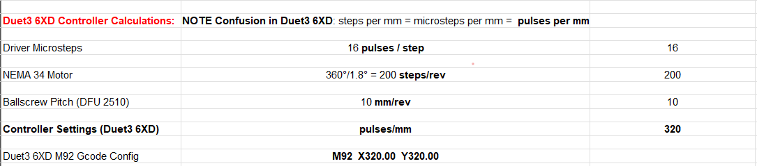
M92 X320.00 Y320.00 Z20.00 U20.00 V20.00 W8.888 A8.888 B8.888 C8.888 D8.888 'G8.888 ; set steps per mm, Ballscrew Pitch 10mm/rev. (X & Y = Currently 3200 pulse/rev / 10 revs = 320 microSteps/mm = 320 pulses/mm) -
@developeralgo222 320 steps per mm looks correct, based on your leadscrew pitch of 10mm and steps per rotation of 3200, and so would be set by M92 X320 Y320 ... etc. Microstepping mode (M350) and driver currents (M906) is not controlled by firmware configuration, as this is set by the driver, so the Duet is just sending steps.
Ballscrews inherently have backlash. You can't account for this by adjusting steps per mm. You either need to provide sufficient preloading of the ballscrew, or use backlash compensation. RepRapFirmware has this built-in, see https://docs.duet3d.com/User_manual/Reference/Gcodes#m425-configure-backlash-compensation
This is a good read on ballscrews: https://www.machinedesign.com/motors-drives/article/21832485/ball-screw-basics-debunking-the-mythsIf you're having positional accuracy issues, you may need to adjust the step timing rate, or jerk (M566), speeds (M203) or accelerations to avoid skipping steps. I note your speed limits are very high for X and Y, at 126000mm/min, or 2.1m/s. You haven't posted the stepper motor timings (M569) so I don't know if this is even achievable. Typically external drivers have a step rate limit of about 200,000Hz, which at 320 steps per mm would be 625mm/s.
Acceleration and jerk settings don't seem too unreasonable, though jerk settings for W, A, B, C, D and 'G seem very high.
Ian
Bed-slinger - Mini5+ WiFi/1LC | RRP Fisher v1 - D2 WiFi | Polargraph - D2 WiFi | TronXY X5S - 6HC/Roto | CNC router - 6HC | Tractus3D T1250 - D2 Eth
-
@droftarts
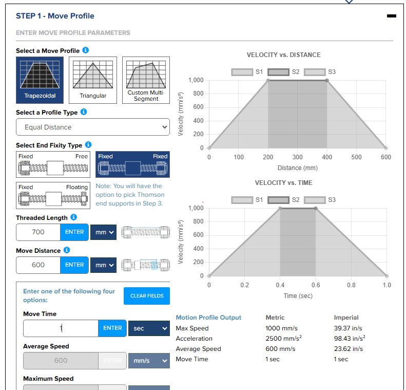
Here it is :; Drives ;Physical Drives CAN ID = 0 M569 P0.0 S0 T5:5:10:10 ; X-Axis physical drive 0.0 goes backwards on CAN ID = 0 - Duet 6XD Drive 0.0 with 2.5us timings between pulses M569 P0.1 S0 T5:5:10:10 ; Y-Axis physical drive 0.1 goes forwards on CAN ID = 0 - Duet 6XD Drive 0.1 with 2.5us timings between pulses M569 P0.2 S1 T5:5:10:10 ; 'H-Axis physical drive 0.2 goes forwards on CAN ID = 0 - Duet 6XD Drive 0.2 with 2.5us timings between pulses (Microstep Driver) ;Physical Drives CAN ID = 1 = All Shared Z Axes (Z, U, V ) each with a single Stepper Motor M569 P1.0 S1 ; Z1 (Z) Axis physical drive 1.0 Rotates Clockwise or Anticlockwise to move CAM driven dual nozzles down and up on Z axis on CAN ID = 1 - Duet 3HC Drive 1.0 M569 P1.1 S1 ; Z2 (U) Axis physical drive 1.1 Rotates Clockwise or Anticlockwise to move CAM driven dual nozzles down and up on U axis on CAN ID = 1 - Duet 3HC Drive 1.1 M569 P1.2 S1 ; Z3 (V) Axis physical drive 1.2 Rotates Clockwise or Anticlockwise to move CAM driven dual nozzles down and up on V axis on CAN ID = 1 - Duet 3HC Drive 1.2 ;Physical Drives CAN ID = 2 = C Axes ( W, A, B ) M569 P2.0 S0 ; C1 (W) Axis physical drive 2.0 Rotates forwards and backwards on CAN ID = 2 - Duet 3HC Drive 2.0 - C 360°-continuous, but linear feed-rate M569 P2.1 S0 ; C2 (A) Axis physical drive 2.1 Rotates forwards and backwards on CAN ID = 2 - Duet 3HC Drive 2.1 - C 360°-continuous, but linear feed-rate M569 P2.2 S0 ; C3 (B) Axis physical drive 2.2 Rotates forwards and backwards on CAN ID = 2 - Duet 3HC Drive 2.2 - C 360°-continuous, but linear feed-rate ;Physical Drives CAN ID = 3 = C Axes (C, D, 'G) M569 P3.0 S0 ; C4 (C) Axis physical drive 3.0 Rotates forwards and backwards on CAN ID = 3 - Duet 3HC Drive 3.0 - C 360°-continuous, but linear feed-rate M569 P3.1 S0 ; C5 (D) Axis physical drive 3.1 Rotates forwards and backwards on CAN ID = 3 - Duet 3HC Drive 3.1 - C 360°-continuous, but linear feed-rate M569 P3.2 S0 ; C6 ('G) Axis physical drive 3.2 Rotates forwards and backwards on CAN ID = 3 - Duet 3HC Drive 3.2 - C 360°-continuous, but linear feed-rate ;By default Z U V W are linear and A B C D are rotary; but you can change that using the R ; set visible drive mapping ; X-Axis , Y-Axis (2 x Nema 34 Closed Loop Motors) and Z-Axes (Z,U,V) mapping to 3 Stepper motors ; directly connected to 3HC (CAN ID = 1) (which moves the nozzles up and down along Z-axis) ; Rotational Axes mapping (W, A, B, C, D, 'G ) to 6 motors directly connected to 3HC (CAN ID 2 and 3) (which rotates the nozzles +180 / -180 along Rotational axis) ; Axes: XYZUVWABCD abcdefghijkl mnopqrstuvwxyz are available in RepRapFirmware 3.5 and later on Duet 3 MB6HC and MB6XD only ; Best results is to configure all Controller Axes as Linear for OpenPNP, even if they are conceptually rotational this allows OpenPnP to control feed-rates, acceleration etc ; with better precision and smooth segments transitions M584 X0.0 Y0.1 Z1.0 U1.1 V1.2 W2.0 A2.1 B2.2 C3.0 D3.1 'G3.2 S0 ; LIN R0 = LINEAR, R1 = ROTATION M350 Z16 U16 V16 W16 A16 B16 C16 D16 'G16 I1 ; configure microstepping with interpolation. Irrelevant for external drives X, Y, & 'B (X & Y = Dip Switches 3200= SW1=ON,SW2=ON,SW3=OFF,SW4=OFF,SW5=ON,SW6=ON) M92 X320.00 Y320.00 Z20.00 U20.00 V20.00 W8.888 A8.888 B8.888 C8.888 D8.888 'G8.888 ; set steps per mm, Ballscrew Pitch = 10mm/rev. (X & Y = Currently 3200 pulse/rev / 10 mm/rev = 320 pulses/mm) M566 X900.0 Y900.0 Z900.0 U900.0 V900.0 W900.0 A900.0 B900.0 C900.0 D900.0 'G900.0 P1 ; set maximum instantaneous speed changes (mm/min) and use Jerk policy 1 M203 X60000.00 Y60000.00 Z24000.00 U24000.00 V24000.00 W3600000.00 A3600000.00 B3600000.00 C3600000.00 D3600000.00 'G3600000.00 ; set maximum speeds/feedrate (mm/min) M201 X5000.00 Y5000.00 Z2000.00 U2000.00 V2000.00 W180000.00 A180000.00 B180000.00 C180000.00 D180000.00 'G180000.00 ; set accelerations (mm/s^2) M906 Z1360.0 U1360.0 V1360.0 W560.0 A560.0 B560.0 C560.0 D560.0 'G560.0 I100 ; set motor currents (mA) and motor idle factor in per cent(I100 = "Always 100% ON = No idle time"). This is irrelevant for external drives (X & Y ) ; M84 S30 ; Set idle timeout M564 H0 ; Sets homing, H0 allows mvmnt wo homing ; Axis Limits M208 X0 Y0 Z-70 U-70 V-70 W-360000 A-360000 B-360000 C-360000 D-360000 'G-360000 S1 ; Set axis minima M208 X335 Y445 Z70 U70 V70 W360000 A360000 B360000 C360000 D360000 'G360000 S0 ; Set axis maximai also just used a tool at https://www.thomsonlinear.com/en/products/ball-screws?solution=motioneering to see what the max might be and if it would work with the values. it seems your value of 625mm/s is within the ballpark of average 600mm/s to 1000 mm/s (Max)
-
Also setting M92 X320 Y320 gives me problems in that the external drivers throw an error and halt the machine during homing. The feedrate might be too high for 320 pulses/mm , i will lower the feedrate and test
-
@droftarts , @dc42 , @T3P3Tony
i have a few stepper motors in my machine that i need to configure correctly all with Max pulse rate of 200 kHz and Step Angle of 1.8 degree. Currently steps/mm is set to 320 for X & Y . Do i need to lower this steps/mm value to something like 100mm/step?
X & Y axis use NEMA 34 Closed loop stepper Motors with external Drivers HSS86
Z,U,V, W, A, B, C, D, 'G axes use Nema 17 & 11 stepper Motors with Duet Internal Driver.I am trying find the correct settings for fast and smoothness with less Jerk . What would be the ideal settings on Duet3 config.g file to achieve this or is there a calculator to do this for Duet boards correctly. i looked at the RRF calculator but it was not ideal for calculating the values
M569 P0.0 S0 T2.5:2.5:2.5:2.5 ; 2.5us timings between pulses for X-axis M569 P0.1 S0 T2.5:2.5:2.5:2.5 ; 2.5us timings between pulses for Y-axis . . . M350 Z16 U16 V16 W16 A16 B16 C16 D16 'G16 I1 ; configure microstepping with interpolation. M92 X320.00 Y320.00 Z20.00 U20.00 V20.00 W8.888 A8.888 B8.888 C8.888 D8.888 'G8.888 ; set steps per mm . Ballscrew Pitch = 10mm/rev. M566 X900.0 Y900.0 Z900.0 U900.0 V900.0 W900.0 A900.0 B900.0 C900.0 D900.0 'G900.0 P1 ; set maximum instantaneous speed changes (mm/min) and use Jerk policy 1 M203 X60000.00 Y60000.00 Z24000.00 U24000.00 V24000.00 W3600000.00 A3600000.00 B3600000.00 C3600000.00 D3600000.00 'G3600000.00 ; set maximum speeds/feedrate (mm/min) M201 X5000.00 Y5000.00 Z2000.00 U2000.00 V2000.00 W180000.00 A180000.00 B180000.00 C180000.00 D180000.00 'G180000.00 ; set accelerations (mm/s^2) M906 Z1360.0 U1360.0 V1360.0 W560.0 A560.0 B560.0 C560.0 D560.0 'G560.0 I100 ; set motor currents (mA) and motor idle factor in per cent -
@developeralgo222 If the step rate is limiting the top speed, yes, you need to reduce the step per mm rate. Reduce the number of steps per rotation on the driver, then adjust M92 the corresponding amount. Yes, this will allow for faster speeds, at the expense of some accuracy between steps. 100 steps per mm (so 1000 steps per revolution) would be 1 step per 100th of a mm, so if that's the accuracy you are looking for, reduce it down to that. Top speed limited by the step rate should correspondingly increase up to roughly 200000/100 = 2000mm/s, or 120000mm/min.
For jerk and acceleration, most calculators will show the acceleration ramp for any particular move. Obviously, short moves may not hit top speed. Jerk is generally not modelled, but is best kept low ie between 5-10mm/s (300-600mm/min), but can depend on the weight of the axes and torque of the motors.
Whether jerk, acceleration and speed are achievable (or cause skipping steps) is really down to testing, and 'smoothness' is largely down to personal preference, though things like mid-band resonance (see https://www.geckodrive.com/support/mid-band-instability/) in the motors can cause issues at specific speeds. Generally you want to find the maximum jerk/speed/acceleration before step loss or motor stall, and probably leave a 20% safety margin. Unfortunately this is very difficult to calculate, because it depends on so many different variables, some inherent and specific to your machine. The Thomson Linear calculator gives some indication what accelerations and top speeds are suitable for ballscrews.
Ian
Bed-slinger - Mini5+ WiFi/1LC | RRP Fisher v1 - D2 WiFi | Polargraph - D2 WiFi | TronXY X5S - 6HC/Roto | CNC router - 6HC | Tractus3D T1250 - D2 Eth
-
i managed to test X & Y with the following configs. Because i modified the External Drivers dip switch settings to 10000 pulses/rev for testing
TESTING for Speed, Acceleration and Jerk for X & Y axis
-
NEMA 34 Stepper 1.8° Motor = 200 pulses/rev
-
Ballscrew Pitch = 10 mm/rev
-
HSS86 Driver microstep setting for X & Y axis with NEMA 34 , 8.0 N.m = 10,000 pulses/rev
-
This gives (10000 pulses/rev ) / (10mm/rev) = 1000 pulses/mm but that's too high so Duet3 config is set to 100 steps/mm i.e M92 X100 Y100 . This results in 10:1 ratio on the openPnP side ( 10mm move on OpenPnP == 1 mm move on actual machine ). Not sure if i need to set OpenPnP side differently from what's on Duet for this ?
-
On OpenPnP side i have X & Y Axis steps/mm set to the same as Duet3 Config.g at 100 steps/mm
Results:
-
Works ok with Max speeds = 1500 mm/s ==> 90000 mm/min but i need to find out how to have OpenPnP movement synced with Duet's so that 1mm move on OpenPnP == 1mm move on Machine axis itself.
-
It's fast and smooth no jerking . Not sure if to drop down to 1000 pulses/rev on the driver from 10000 pulses/rev in order to have 1:1 ratio between OpenPnP & Duet settings.
-
With microstepping at 1000 pulses/rev on HSS86 Driver. its a a little jerky and stalls the motor or error the drive with any feed rate abovet 6000 mm/min
M569 P0.0 S0 T2.5:2.5:2.5:2.5 ; 2.5us timings between pulses for X-axis M569 P0.1 S0 T2.5:2.5:2.5:2.5 ; 2.5us timings between pulses for Y-axis . . . M350 Z16 U16 V16 W16 A16 B16 C16 D16 'G16 I1 ; configure microstepping with interpolation. M92 X100.00 Y100.00 Z20.00 U20.00 V20.00 W8.888 A8.888 B8.888 C8.888 D8.888 'G8.888 ; set steps per mm . Ballscrew Pitch = 10mm/rev. M566 X900000.0 Y900000.0 Z900.0 U900.0 V900.0 W900.0 A900.0 B900.0 C900.0 D900.0 'G900.0 P1 ; set maximum instantaneous speed changes (mm/min) and use Jerk policy 1 M203 X90000.00 Y90000.00 Z24000.00 U24000.00 V24000.00 W3600000.00 A3600000.00 B3600000.00 C3600000.00 D3600000.00 'G3600000.00 ; set maximum speeds/feedrate (mm/min) M201 X5000.00 Y5000.00 Z2000.00 U2000.00 V2000.00 W180000.00 A180000.00 B180000.00 C180000.00 D180000.00 'G180000.00 ; set accelerations (mm/s^2) M906 Z1360.0 U1360.0 V1360.0 W560.0 A560.0 B560.0 C560.0 D560.0 'G560.0 I100 ; set motor currents (mA) and motor idle factor in per cent -
-
@developeralgo222 said in Correct way to set Steps Per mm for X and Y:
This gives (10000 pulses/rev ) / (10mm/rev) = 1000 pulses/mm but that's too high so Duet3 config is set to 100 steps/mm i.e M92 X100 Y100 .
You've gone the other way, with MORE steps per revolution, so you need MORE pulses per second. You would set M92 X1000 Y1000. Not sure what you mean by "but that's too high". Your max speed will be more limited than before.
If 1000 pulses/rev is jerky, try 1600 pulses/rev, ie 200 full steps per revolution * 8 microsteps (1000 pulses/rev gives 5 microsteps between full steps). M92 X160 Y160.
Ian
Bed-slinger - Mini5+ WiFi/1LC | RRP Fisher v1 - D2 WiFi | Polargraph - D2 WiFi | TronXY X5S - 6HC/Roto | CNC router - 6HC | Tractus3D T1250 - D2 Eth
-
Do you mean setting steps /mm on Duet to 1000 steps/mm ? i.e
M92 X1000 Y1000 ? as you said it will limit the speed. i think my problem is that it seems 100 steps/mm ( 1000 pulses/rev) is fine . But when i enter that value on the X & Y axis on the OpenPnP side its on 10:1 ratio . That is 10mm move on the OpenPnP software /Duet DWC console actually moves machine X & Y 1 mm physically i.e 10:1 ratio. That creates a few issues with OpenPnP configuration , it assumes 1:1 relation in steps/mm that is configured on Duet3 as it uses it for other movements like backlash calculations etc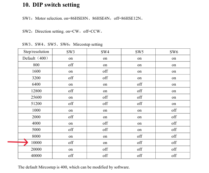
-
@developeralgo222 Set M92 to whatever you set the driver pulses/rev to, divided by 10. eg 10,000 pulses/rev = M92 X1000, 3,600 pulses/rev = M92 X360, 1,000 pulses/rev = M92 X100. Then it should be a 1:1 relationship. You can't cheat the numbers to get performance, because you always have to send the step pulses to the motor, it's just the scaling that will be wrong.
I don't know why OpenPNP changes to a 10:1 relationship when it drops low, you'll have to ask them.
Ian
Bed-slinger - Mini5+ WiFi/1LC | RRP Fisher v1 - D2 WiFi | Polargraph - D2 WiFi | TronXY X5S - 6HC/Roto | CNC router - 6HC | Tractus3D T1250 - D2 Eth
-
@droftarts
Fantastic thanks for that clarification. So from your explanation it implies that the Higher "steps/mm" number on Duet M92 Xnnn Ynnn ===> The Lower the speed /Feedrate (Limited Speed) ? -
Can you confirm . I just tested with Duet DWC Console ( Not involving OpenPnP at all)
HSS86 Driver is set to 10000 pulses/rev == (10000 pulses/rev ) / 10 mm/rev = **Maximum Possible/allowed of 1000 pulses/mm at 10000 pulses/rev HSS86 Driver setting **
Test 1: M92 X1000 Y1000 get 1:1 relation with Max Speed = 200 mm/s == 12000 mm/min before stall/skip
G1 H2 X100 F12000Test 2: M92 X100 Y100 get 10:1 relation with Max Speed = 2000 mm/s == 120000 mm/min before stall/skip
G1 H2 X100 F120000This seems to indicate that the HSS86 Driver set value using DIP Switch to 10000 pulses/rev == 1000 pulses/mm is simply maximum reference value allowed at that setting as per the Ballscrew Pitch.
So if you configure something like M92 X50 Y50, i.e 50 steps/mm on Duet then Duet will send that along to the driver and since the driver is expecting 10000 pulses/rev == 1000 pulses/mm, it takes that (1000 pulses(steps)/mm ) / 50 steps/mm = 20 . i.e every measurement on Duet in relation to X & Y axis motor movements will be in 20:1 ratio as per this example where 200mm on Duet will move 10 mm on actual Machine
G1 H2 X200 F100000At first i thought it was Duet /OpenPnP but i just realized its not. The ratio occurs depending on what Duet/OpenPnP send to the HSS86 external driver and the HSS86 Driver calculates the measurement ratio for moving the motor
Since i am able to configure a lower value of M92 X100 Y100 and it works fine and sends that lower steps/mm value from Duet DWC to the driver towards the motor creating 10:1 ratio measurement.
This test outcome is a surprise to me.
-
@developeralgo222 I think it's doing exactly what I'd expect it to do. The Duet doesn't know how you have set the driver pulses/rev. If you set it to 10000, and M92 X100 Y100, and command 100mm, it will send 100 (steps per mm) * 100 (mm), so 10000 steps. So the driver will move one revolution, ie 10mm of the ballscrew. As far as the Duet is concerned, it moved 100mm, and the speed and acceleration calculations will be based on that. Whatever is reported in DWC is x10 overstated. What are you struggling with here? The driver is not calculating "the measurement ratio for moving the motor", it's just moving how many steps it receives.
Ian
Bed-slinger - Mini5+ WiFi/1LC | RRP Fisher v1 - D2 WiFi | Polargraph - D2 WiFi | TronXY X5S - 6HC/Roto | CNC router - 6HC | Tractus3D T1250 - D2 Eth
-
@droftarts
I think you clearly explained it to me . i was struggling to understand the link & calculations as to why if i sent a command of 100mm and i have HSS86 Driver with 10000 pulses/rev and M92 X100 Y100 configured . what was going on .That's clearly explained now i see why i was getting all confused about the command and the steps/mm calculations
Thanks so much for explaining that clearly
-
Thanks for your help. Here is what i have adjusted them to
M569 P0.0 S0 T2.5:2.5:2.5:2.5           ;  2.5us timings between pulses for X-axis
M569 P0.1 S0 T2.5:2.5:2.5:2.5           ;  2.5us timings between pulses for Y-axis
.
.
.
M350 Z16 U16 V16 W16 A16 B16 C16 D16 'G16 I1         ; configure microstepping with interpolation.
M92 X100.00 Y100.00 Z80.00 U80.00 V80.00 W8.888 A8.888 B8.888 C8.888 D8.888 'G8.888     ; set steps per mm . Ballscrew Pitch = 10mm/rev.
M566 X900.0 Y900.0 Z900.0 U900.0 V900.0 W900.0 A900.0 B900.0 C900.0 D900.0 'G900.0  P1     ; set maximum instantaneous speed changes (mm/min) and use Jerk policy 1
M203 X51000 Y51000 Z6000 U6000 V6000 W3600000.00 A3600000.00 B3600000.00 C3600000.00 D3600000.00 'G3600000.00    ; set maximum speeds/feedrate (mm/min)
M201 X5000.00 Y5000.00 Z2000.00 U2000.00 V2000.00 W180000.00 A180000.00 B180000.00 C180000.00 D180000.00 'G180000.00     ; set accelerations (mm/s^2)
M906 Z1360.0 U1360.0 V1360.0 W560.0 A560.0 B560.0  C560.0 D560.0 'G560.0  I100        ; set motor currents (mA) and motor idle factor in per cent
As concerns Jerk , Duet measurement are in mm/min but openPnP are in mm/s^3
in order to convert that into mm/s^3 for OpenPnP do i just need to take Duet's config value and multiply by (60 * 1/S^3 )
i.e 900 mm/min = 900 x 60 mm/s =54000 mm/s x (1/s^2) = 54000 mm/s^3
is this correct assumption ? or Both Duet & OpenPnP must have be synchronized by having same Value ?
From this config is there anything you think might be a little out of place i.e Too high or too low