Reading Sensor Pressure from Analog output
-
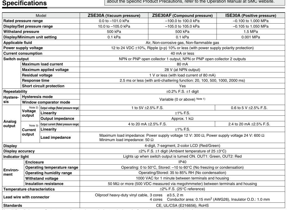
I have SMC ZSE30A-01-C Pressure Sensors with 1 NPN output (Black) + Analog voltage output (white wire) and have configured them with M308 Commands, and also according to the datasheet ZSE30A_ISE30.pdf
M308 S1 P"2.io0.in" Y"linear-analog" A"VG1" F0 B0.0 C-101 M308 S1 P"2.io1.in" Y"linear-analog" A"VG2" F0 B0.0 C-101 M308 S1 P"2.io2.in" Y"linear-analog" A"VG3" F0 B0.0 C-101 M308 S1 P"3.io0.in" Y"linear-analog" A"VG4" F0 B0.0 C-101 M308 S1 P"3.io1.in" Y"linear-analog" A"VG5" F0 B0.0 C-101 M308 S1 P"3.io2.in" Y"linear-analog" A"VG6" F0 B0.0 C-101 More info:
 .
.
I am able to read the values but they are wrong . Are offset by almost -38 , Actual Value = 0.0 while the reading returns -38 or -37.x as the value
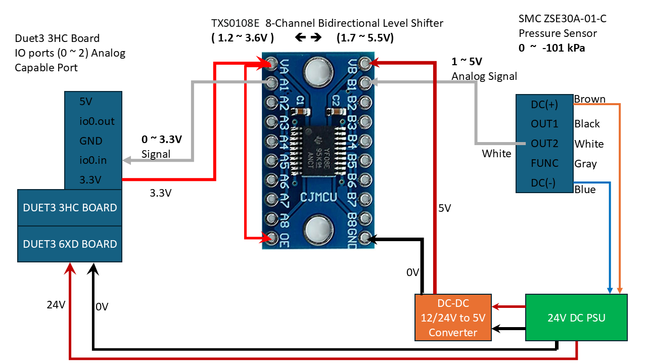
Duet3 Analog ports on 3HC (0 to 3.3V signal) ====> isolated 8-Port channel Bidirectional Level Shifter 3.3V to/from 5V ==> SMC ZSE30A-01-C Analog port ( 1 - 5V signal).
How do i configure this correctly ?
i was also looking at an Old Arduino code to see if i can get some help from that :
SMC vacuum sensor ZSE30A-01-C-L =============================================== ARDUINO CODE =============================================== // 1 Volt is an ADC value of ~205 with a 10-bit ADC and 5V Aref const int offset = 205; // calibrate zero pressure Kpa = (analogRead(A0) - offset) * 101 / (1023 - offset); I have managed to fiddle a round and get to this to try solve my issue but i am not sure if this is the correct way to configure it.
M308 S1 P"2.io0.in" Y"linear-analog" A"VG1" F0 B0.0 C-101 V0.00 U13.5 M308 S1 P"2.io1.in" Y"linear-analog" A"VG2" F0 B0.0 C-101 V0.00 U13.5 M308 S1 P"2.io2.in" Y"linear-analog" A"VG3" F0 B0.0 C-101 V0.00 U13.5 M308 S1 P"3.io0.in" Y"linear-analog" A"VG4" F0 B0.0 C-101 V0.00 U13.5 M308 S1 P"3.io1.in" Y"linear-analog" A"VG5" F0 B0.0 C-101 V0.00 U13.5 M308 S1 P"3.io2.in" Y"linear-analog" A"VG6" F0 B0.0 C-101 V0.00 U13.5 i got adjusted values at 0.0 kPa that now fall within expected readings (-0.1 - 0.1 ) kPa but i still need to test with actual air pressure running through to see what the values are going to be and if they conform to the Adjusted Reading e.g is Actual -50.0 kPa pressure reading on the sensor going to be read as -50.0 (+/- 0.2) kPa with the adjusted reading or it will skew or extremely deviate from the actual sensor displayed values.
11/14/2024 , 12:24:15 PM M308 S1 Sensor 1 (VG1 Pressure) type Linear analog using pin 2.io0.in, last error ok, offset adjustment 13.5, slope adjustment 0.000, adjusted reading -0.1, unfiltered, range 0.0 to -101.0 Here is brief snapshot of my connections :
-
@developeralgo222 Sorry, I was going to get back to you and say use the V and U parameters to adjust the offset, but looks like you found them already. While it says 'Temperature reading offset' in the Gcode dictionary entry for M308, I think it can be used to offset any reading.
Ian
-
at 0.0 kPa those above values work but they extremely skewed as you start to have pressure reading. i am not sure what are the correct values to have it working .
e.g Actual Sensor Display = 0.0 Kpa , Duet Adjusted Reading = 0.0 kPa But
Actual Sensor Display =70.0 kPa , Duet Adjusted Reading = 86.8 kPai then let it run and kept reading the observing the values compared to what is being read. The Duet readings don't change that much while the actual pressure is decreasing. I am not sure if Adjusted reading formula actually works with Pressure sensor readings
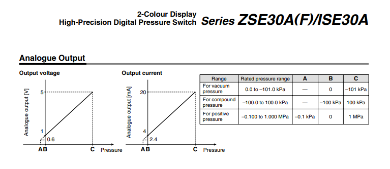
in a simple way of y = ax+b ==> a = slope & b = offset , y = Voltage (1 ~ 5V ) and X = Pressure ( 0 ~ -101.0 kPa )
i.e y = 0.043x + 0.6 ===> x = (y/0.043 ) - (0.6/0.043) ==> x = 23.25y - 13.90
- Looking the formula AdjustedReading = (RawReading * (1.0 + V)) + U
But if i equate 1.0+V = 23.25 ==> V = 22.25 & U = -13.90
i get an error that V is "Too High".
What are the ranges of V & U ?
-
@developeralgo222 I can't find in the firmware where the minimum and maximum values for U and V are set. I've asked @dc42 to check.
Ian
-
As per my testing i don't think Analog port on Duet3 3HC seems to be working correctly. It seems that as per the Analog connection , i should be getting varied Analog pressure reading from the Sensor but it looks like its behaving as if it only triggers to a Max Value set when the Set pressure is met or it remains at the Minimum set Value so long as the Set pressure on the sensor is not yet met. Its behaving more like a NPN output instead or analog output .
E.g i have this on Duet3
M308 S1 P"2.io0.in" Y"linear-analog" A"VG1" F0 B0.0 C-101 V0.0 U13.5and on SMC Pressure Sensor i have set it to - 40 kPa for testing
When the
-
Sensor reads/displays 0.0 ~ -39.9 kPa =====> Duet reads -0.1 ~ 0.1
-
Sensor reads/displays -40.0 ~ -101 kPa =====> Duet reads -87.5 ~ -87.9
it seems to be behaving like a digital NPN output yet its analog output
-
-
@developeralgo222 Try one of the other io.in ports. See https://docs.duet3d.com/Duet3D_hardware/Duet_3_family/Duet_3_Expansion_3HC#inputoutput
Or connect it to a 6XD io.in port to check.Ian
-
-
@developeralgo222 Have you measured the input and output voltages at the level shifter? So the analogue in signal and the corresponding shifted voltage? What are they at say 0, 40 101 KPa? I'm not sure that device is intended to operate in the way you are using it, from the datasheet "The TXS0108E device is a directionless voltage-level translator specifically designed for translating logic voltage levels.". Not sure it is intended to convert an analogue signal that varies over a entire range.
-
@gloomyandy . Any suggestion of a solution if a Logic level shifter is not the right solution ?
AFAIK, these are the recommended solutions to solve this issue. Are you suggesting anything different from this?
-
Voltage Divider ( simple but not robust)
-
Bi-directional Logic Level Shifter ( Robust )
-
Zener Diode Clamp
-
Opto-isolator
-
-
@developeralgo222 I would have a thought that a voltage divider would be fine for this sort of application (reducing the range of an analogue voltage), after all that is exactly what is used to measure the supply voltage on a Duet board. Do you have a reference that gives details as to why a divider would not work?
-
@developeralgo222 @dc42 says
U is limited to the range -20.0 to +20.0. V is limited to the range -0.2 to +0.2.
If this range isn't big enough, let us know, though it sounds like the voltage conversion isn't quite working correctly.
Ian
-
@droftarts
Thanks Ian, i have tried connecting directly & through a level Shifter and none seems to work correctly .I am sure i am not the only one who has dealt or is dealing with this issue on Duet3 boards.
How to correctly read Pressure Sensor values either using a Digital NPN output signal ( 1 =True , 0=False) or Analog Voltage/Current Signal output ( Variable range ). i have made the connections and double checked everything but can't get it to work on Duet3 Boards but it works great on my Arduino and other boards no issues at all.
-
@gloomyandy , Voltage divider is simple and works most of the time (Dividers tend to be unreliable sometimes when you need accuracy ) but i have 6 sensors that are connected and are being used as Vacuum Pressure Sensing Actuators for my Pick-and-Place machine . i need high accuracy and robust reliability , that's why i used a Voltage Level Shifter
-
@developeralgo222 Have you actually measured the voltages on each side of the level shifter you are currently trying to use? That is really the first step and should be easy to do.
-
@gloomyandy Yes i did before i plugged everything in . 5V on the High side and 3.3V on the low side. Let me just do it again to see if that changed with the load
-
@developeralgo222 You need to do it at various different pressure readings so we can see what the transfer function of the level shifter looks like.
-
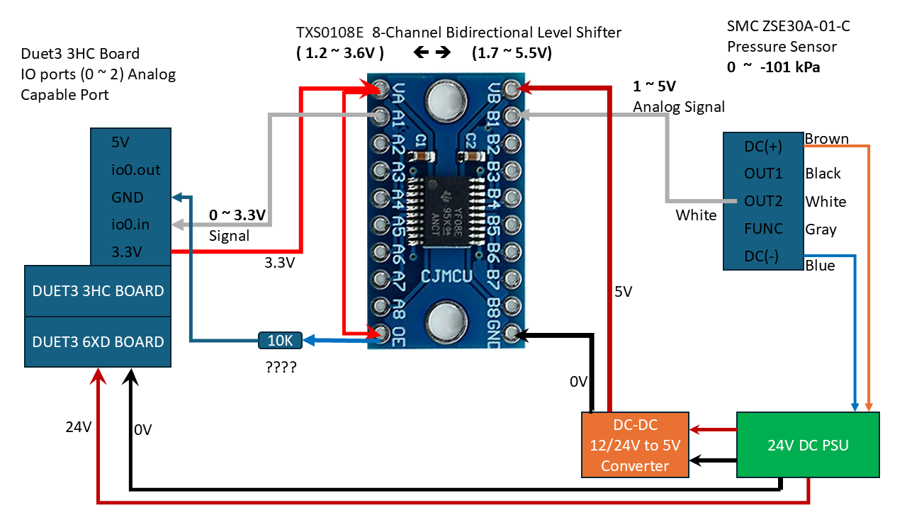
@gloomyandy , ok will do that. Quick question, Do i need to connect a 10K resistor between the 3.3V converter source i.e Tie VA(3.3V) to OE then to 10K resistor to GND as per the TXS0108E Datasheet ?
-
i need high accuracy and robust reliability , that's why i used a Voltage Level Shifter
The level shifter you want to use is inappropriate for the task: as @gloomyandy says, the TXS0108E translates logical (i.e. ”binary”) signals from one voltage level to another one. Please study the data sheet to understand what this device is intended to do. On page 17, they say explicitly what they do to your analog signal:
When transmitting data from A-ports to B-ports, during a rising edge the one-shot circuit (OS3) turns on the PMOS transistor (P2) for a short-duration which reduces the low-to-high transition time. Similarly, during a falling edge, when transmitting data from A to B, the one-shot circuit (OS4) turns on the N-channel MOSFET transistor (N2) for a short-duration which speeds up the high-to-low transition.
So, they don’t shift an analog voltage to another level, instead, they try to detect flanks and sharpen these for better digital signal quality. For your use case, that’s the opposite of ”high accuracy”.
A simple voltage divider is what you need. Using high-quality resistors, these are very accurate and highly reliable. I really have no clue why you disqualify them as ”simple but not robust”. The contrary is true. Towards @gloomyandy, you mention three alternative solutions: ”Zener Diode Clamp” and ”Opto-isolator”. Both are counter-productive: With a Z-diode, you can clip (or limit) a voltage, an opto-isolator is highly non-linear. Your preferred solution, a ”Bi-directional Logic Level Shifter”, falls in the same category.
If you don’t like voltage dividers at all, there is an alternative: Op-Amps. But designing a circuit with several discrete components is a major task and not worth the effort: any added accuracy is easily ruined by the subsequent A/D conversion on the Duet controller or by temperature shifts along all components in the signal path.
-
i can't seem to get a good voltage divider to purchase that can handle 6 outlets. Do you have any link of any voltage divider that can do that and is being sold anywhere ? i don't have time to design one at the moment
-
i can't seem to get a good voltage divider to purchase that can handle 6 outlets.
I’m not aware of a commercial product either. Just mount 12 resistors on a perfboard - that’s it.