Reading Sensor Pressure from Analog output
-
@developeralgo222 @dc42 says
U is limited to the range -20.0 to +20.0. V is limited to the range -0.2 to +0.2.
If this range isn't big enough, let us know, though it sounds like the voltage conversion isn't quite working correctly.
Ian
-
@droftarts
Thanks Ian, i have tried connecting directly & through a level Shifter and none seems to work correctly .I am sure i am not the only one who has dealt or is dealing with this issue on Duet3 boards.
How to correctly read Pressure Sensor values either using a Digital NPN output signal ( 1 =True , 0=False) or Analog Voltage/Current Signal output ( Variable range ). i have made the connections and double checked everything but can't get it to work on Duet3 Boards but it works great on my Arduino and other boards no issues at all.
-
@gloomyandy , Voltage divider is simple and works most of the time (Dividers tend to be unreliable sometimes when you need accuracy ) but i have 6 sensors that are connected and are being used as Vacuum Pressure Sensing Actuators for my Pick-and-Place machine . i need high accuracy and robust reliability , that's why i used a Voltage Level Shifter
-
@developeralgo222 Have you actually measured the voltages on each side of the level shifter you are currently trying to use? That is really the first step and should be easy to do.
-
@gloomyandy Yes i did before i plugged everything in . 5V on the High side and 3.3V on the low side. Let me just do it again to see if that changed with the load
-
@developeralgo222 You need to do it at various different pressure readings so we can see what the transfer function of the level shifter looks like.
-
@gloomyandy , ok will do that. Quick question, Do i need to connect a 10K resistor between the 3.3V converter source i.e Tie VA(3.3V) to OE then to 10K resistor to GND as per the TXS0108E Datasheet ?
-
i need high accuracy and robust reliability , that's why i used a Voltage Level Shifter
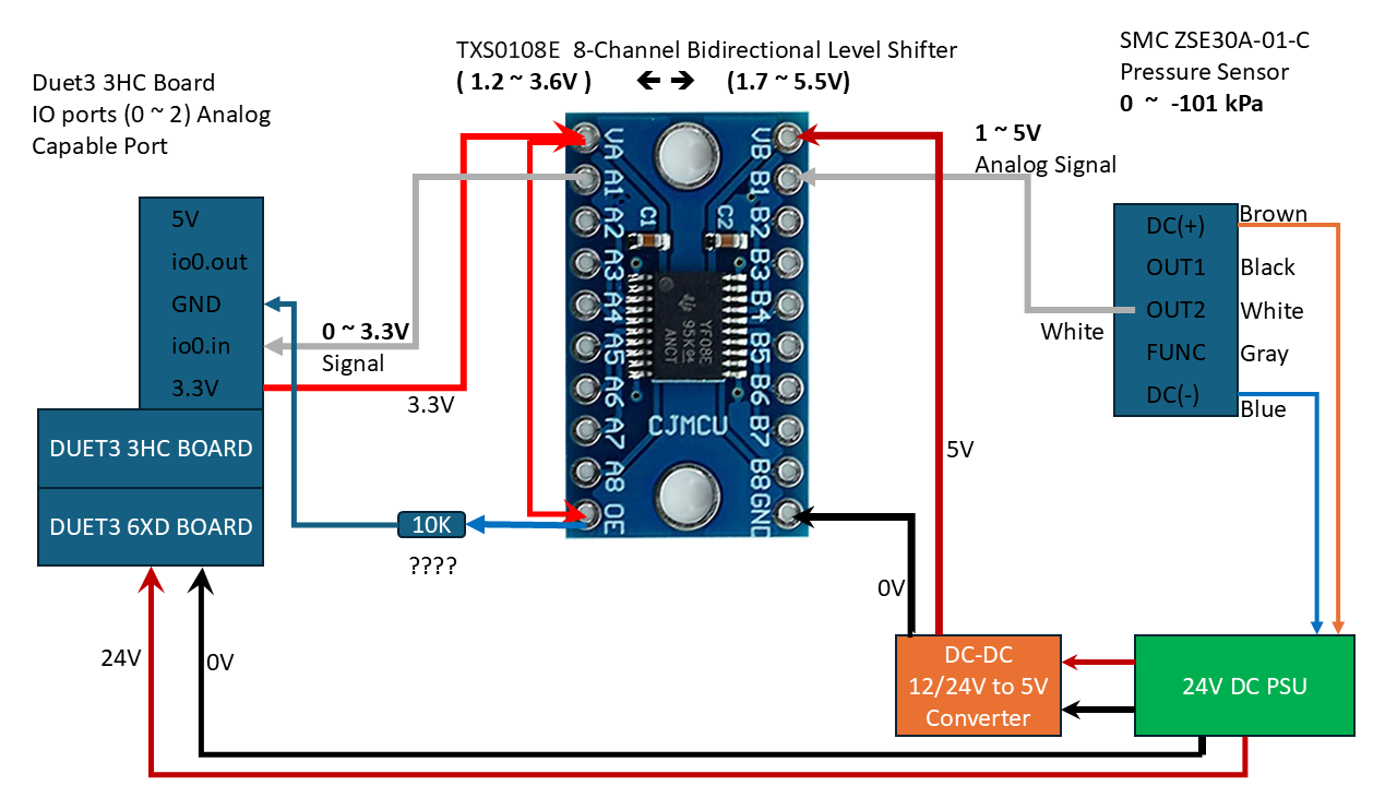
The level shifter you want to use is inappropriate for the task: as @gloomyandy says, the TXS0108E translates logical (i.e. ”binary”) signals from one voltage level to another one. Please study the data sheet to understand what this device is intended to do. On page 17, they say explicitly what they do to your analog signal:
When transmitting data from A-ports to B-ports, during a rising edge the one-shot circuit (OS3) turns on the PMOS transistor (P2) for a short-duration which reduces the low-to-high transition time. Similarly, during a falling edge, when transmitting data from A to B, the one-shot circuit (OS4) turns on the N-channel MOSFET transistor (N2) for a short-duration which speeds up the high-to-low transition.
So, they don’t shift an analog voltage to another level, instead, they try to detect flanks and sharpen these for better digital signal quality. For your use case, that’s the opposite of ”high accuracy”.
A simple voltage divider is what you need. Using high-quality resistors, these are very accurate and highly reliable. I really have no clue why you disqualify them as ”simple but not robust”. The contrary is true. Towards @gloomyandy, you mention three alternative solutions: ”Zener Diode Clamp” and ”Opto-isolator”. Both are counter-productive: With a Z-diode, you can clip (or limit) a voltage, an opto-isolator is highly non-linear. Your preferred solution, a ”Bi-directional Logic Level Shifter”, falls in the same category.
If you don’t like voltage dividers at all, there is an alternative: Op-Amps. But designing a circuit with several discrete components is a major task and not worth the effort: any added accuracy is easily ruined by the subsequent A/D conversion on the Duet controller or by temperature shifts along all components in the signal path.
-
i can't seem to get a good voltage divider to purchase that can handle 6 outlets. Do you have any link of any voltage divider that can do that and is being sold anywhere ? i don't have time to design one at the moment
-
i can't seem to get a good voltage divider to purchase that can handle 6 outlets.
I’m not aware of a commercial product either. Just mount 12 resistors on a perfboard - that’s it.
-
@developeralgo222 if you don't need isolation between the sensor and the Duet, just use 2 resistors as a voltage divider.
A better solution would be to use sensors that provide a digital interface that the Duet can use, for example Modbus RTL via RS485. You cold put all 6 sensors on the same RS485 bus provided that the sensors provide a way to set then all to different slave addresses.
We have a small number of prototype 2-channel ADC daughter boards designed for reading 0 to 10V signals.
-
Managed to mount 12 resistors ( that i had in hand creating 6 Voltage Dividers ( 1.8K & 3.3K ) per connection and it seems to work read the values fine now . Now my issue is how to Calibrate it correctly .
Sensor Analog ( 1 ~ 5V) ===> Duet Analog ( 0 ~ 3V getting a Max of 3.24V) . Ideally probably i need to use 1.7K resistor so at get 3.3V or 1.6K resistor(assuming leakage or noise) to get 3.33V
@ 0 kPa on the Sensor ===> Duet reads -22 kPa
@ 40 kPa on Sensor ===> Duet reads -38 kPa
@ 55 kPa on Sensor ==> Duet reads -53 kPa
@ 65 kPa on Sensor ==> Duet reads -63 kPa
and so on
Not sure how to calibrate it correctly using U & V values for adjusted reading
-
@developeralgo222 for a linear analog sensor you should leave U and V as zero. Adjust the B and C parameters to get the correct readings.
-
Managed to mount 12 resistors ( that i had in hand creating 6 Voltage Dividers ( 1.8K & 3.3K ) per connection
The nominal values of the two resistors are fine. Depending on the resistor’s specs, the effective values may come with enormous tolerances of up to 20%, so in order to get identical readings on all six channels, you should use resistors with a tolerance of 1% (”E96”) or better (”E192”). Alternatively, you can hand-pick resistors with the help of a multimeter.
Now my issue is how to Calibrate it correctly .
Which M308 command do you apply? Is it still this one from your OP:
M308 S1 P"2.io0.in" Y"linear-analog" A"VG1" F0 B0.0 C-101 V0.00 U13.5If I understand the ”Analogue Section” from the data sheet you provided in the OP correctly, the output voltage at 0.0 kPa is somewhere between 0.6 and 1V (but not 0V). The resulting range should span about 0.5 to 3.2 V. Assuming that you want the Duet to report negative values, the Bnnn parameter (”The temperature or other value when the ADC output is zero”) should be positive (with U at 13.5, try 22), not 0.0. Similarly, Cnnn (”The temperature or other value when the ADC output is full scale”) should be a bit larger, as the output will rarely reach 3.3V.
Think of Bnnn / Cnnn as defining an absolute scale (for 0.0 - 3.3 V), the effective readings being a subset (0.5 - 3.2 V) of that range.
-
currently i only have
M308 S1 P"2.io0.in" Y"linear-analog" A"VG1" F0 B0.0 C-101 V0.0 U0.0i am not using U & V as @dc42 mentioned above.
If i understand what you explained above would this work for the subset range
i will test it but would this work as my start of testing
M308 S1 P"2.io0.in" Y"linear-analog" A"VG1" F0 B22 C-123 V0.0 U0.0OR
M308 S1 P"2.io0.in" Y"linear-analog" A"VG1" F0 B22 C-101 V0.0 U0.0and also do i need to include U & V values in the M308 command if both the values are at 0.0 ? or i can leave them out and just use B & C values like this and no worry about including U & V on the command
M308 S1 P"2.io0.in" Y"linear-analog" A"VG1" F0 B22 C-123 -
i am not using U & V as @dc42 mentioned above.
That’s good, @dc42’s post was short but precise.
i will test it but would this work as my start of testing
M308 S1 P"2.io0.in" Y"linear-analog" A"VG1" F0 B22 C-123 V0.0 U0.0Yes, that’s a good starting point. Don’t stick with the idea to define the minimum and/or maximum of absolute values in Bnnn / Cnnn. Instead, adjust these until the result reads 0 for 0 kPa and -101 for 101 kPa. So, if at 0 kPa, you get a value >0, lower B - or, if you read <0, enlarge B. Then, adjust C in the same way. However, you will notice that if you change C, the reading for 0 kPa will also change a bit. So, it's an iterative process with a lot of try and error.
-
@infiniteloop Thanks guys for the help i will test it this weekend
-
undefined infiniteloop referenced this topic 29 Nov 2024, 13:41