3.6.0B4 object model calibration final deviation value
-
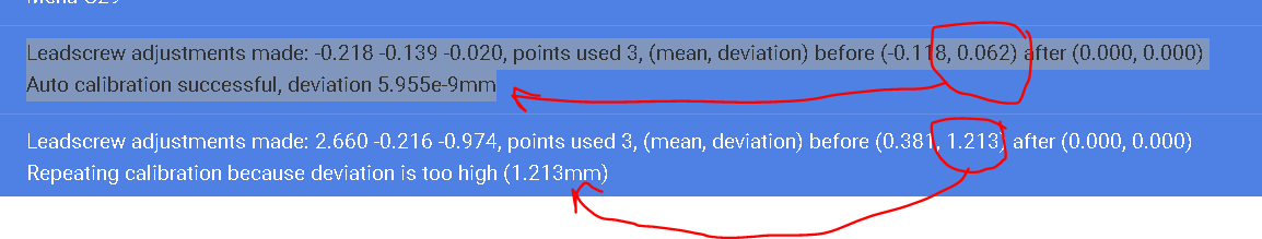
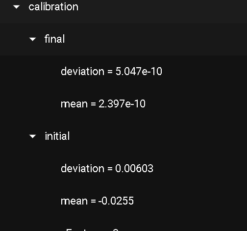
in the new beta versions v6.3.0 the value displaying the final deviation value has changed from mm rounded to 3 decimal places to a scientific notation format , will it be like this in the future or is this a mistake?
v3.5.3
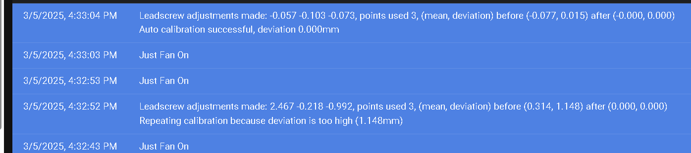
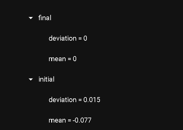
v3.60b2
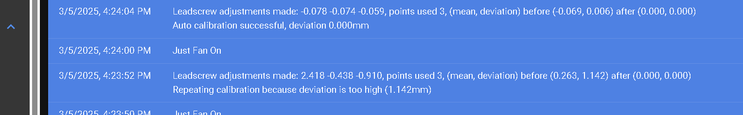
v3.6.0b4
it would be nice to select the number of decimal places , but as it was was ok
-
 undefined moth4017 referenced this topic
-
@moth4017 in RRF 3.5 and earlier, each floating point field in the object model is displayed to a set number of decimal places. This has some undesirable consequences, for example the C parameter in the thermistor configuration is reported as zero whereas in reality it has a small but very significant value. For this reason, RRF 3.6 reports very small values in scientific notation instead. What's happening here is that because of floating point rounding error, the final deviation is computed as a very small number instead of zero, which is why 3.6 reports it in scientific notation.
BTW if you use more probe points than leadscrews, the final deviation won't be zero, which is why we report it.
Duet WiFi hardware designer and firmware engineer
Please do not ask me for Duet support via PM or email, use the forum
http://www.escher3d.com, https://miscsolutions.wordpress.com -
@dc42 Why would i use more then points than lead screws to tram the bed ?
-
@moth4017 if the bed isn't completely flat then probing just 3 points may not give the best level, for example one of the probe points might be on a high spot and another on a low spot. If you probe more points then RRF chooses the plane that minimises the total RMS deviation at the probe points. This in turn is likely to reduce the mesh compensation needed.