Odd bed mesh
-
My diy printer is 600x600 build plate. I have 4 independent z ball screws. G32 is configured to loop until it gets to 0.0075 precision. That runs fine. When I run a mesh afterwards it shows the bed is high in the max y area, when I do the mesh 8x8 the variance is about .3 as if the bed is tilted in the end y travel. I switched to a 4x4 mesh, and the deviation is less than .1. Also the 8x8 bed mesh is wrong, 4x4 mesh looks accurate. I'm using a bl touch, could this be some bounce issue in bl touch, the more points I use the more wrong the mesh is.
-
How many points are you probing for the bed leveling process.
I use three because the beds on my printers have but three adjustments.
Yet just getting those three points to be on a plane can ignore all sorts of out-of-flat conditions that don't show up until you create a height map.
One of my beds appears to be slight bent in the right rear corner, as it levels fine, but the heightmap curves up and that corner.
You should create a 20 x 20 over as much of the bed as you can to see what it looks like.
You might be surprised at how bumpy the bed can be.
Consider these. The first one needs leveling but the second one is as level as it is going to get. The probe/adjustment points are at the rear-left, front-center and rear-right, and I think you can see the bed looks like it is twisted along a line running from front to back near the center.
Frederick
-
@fcwilt you can use more than 3 probe points when levelling the bed, to get a better average sense of level.
Duet WiFi hardware designer and firmware engineer
Please do not ask me for Duet support via PM or email, use the forum
http://www.escher3d.com, https://miscsolutions.wordpress.com -
-
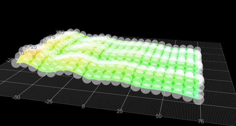
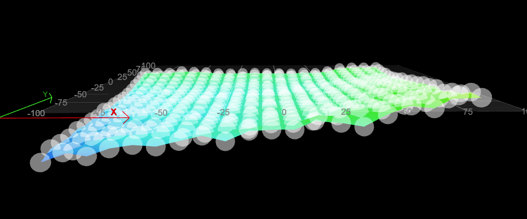
@dc42 I'll post images of my mesh later -- a print is running, 9x9 mesh clearly shows points which were calibrated 4 lead screw level g32 command to 7.5 microns as being more than 200 microns away from each other, and when a print starts its clear that mesh is wrong, its adjusting to that mesh and Y max travel is not sticking to the bed and Y min is over squished -- as it's compensating over 200 micron variance which isn't there. 5x5 grid shows mean error of 6 microns and RMS error of 72 microns and looked good to print. Something is clearly not right as number of probe points increase. I'd like to give a go redesign the primary toolhead to accept a the scanning probe. Wondering if there are plans to true zero like beacon/cartographer do to auto calibrate my understanding all they're doing is measure variations in eddy currents until they stop changing meaning nozzle touched the bed.
-
@kazolar said in Odd bed mesh:
Wondering if there are plans to true zero like beacon/cartographer do to auto calibrate my understanding all they're doing is measure variations in eddy currents until they stop changing meaning nozzle touched the bed.
From the 3.6.0-beta.3 release notes:
[Duet 3] Experimental support for using supported scanning inductive Z probes (i.e. Duet3D Scanning Z Probe and
TOOL1RR tool board) in touch mode is available. This support is enabled using the new M558.3 command.
See https://docs.duet3d.com/en/User_manual/Tuning/scanning_z_probe_calibration#using-the-szp-in-touch-mode-to-set-z-height.
Use it with caution!