HY VFD controlled by Duet 3 Mini
-
@dhusolo you have a frequency to voltage converter, however what you need to interface the Duet spindle control to a VFD with 0-10V input is a PWM to voltage converter. See https://docs.duet3d.com/en/User_manual/Machine_configuration/Configuration_CNC#connecting-a-spindle.
Note, when fed from the 10V supply on the VFD these devices can't supply as much as 10V output, so the full spindle speed is not available.
With the frequency to PWM converter that you have, you would need to adjust the Q parameter in the M950 command that set up the port in order to vary the speed.
In future we expect to support control of spindles via Modbus RTU. If your VFD supports the Modbus commands described in the manual you linked to then control over Modbus may be possible in future.
Duet WiFi hardware designer and firmware engineer
Please do not ask me for Duet support via PM or email, use the forum
http://www.escher3d.com, https://miscsolutions.wordpress.com -
@dc42 You sir are correct. I did get the wrong board. I installed an actual PWM to Voltage converter and wired it up. This is the one I'm using now
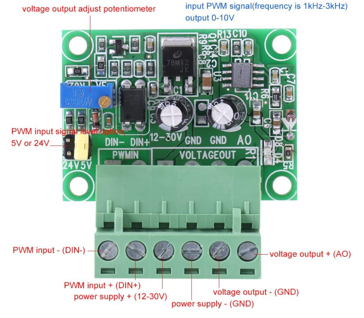
Voltage output - (GND) goes to ACM
Voltage output + (AO) goes to VI(I've also tried AI)I have a relay connected
NO > DCM
COM > FOR
Right now I'm switching it with a macro but eventually I'll get it configured to automatically switch when the drive is working correctly. I know the relay is working because when I switch it on the FOR LED on the VFD goes to solid.
I set:
PD001 = 1
PD002 = 1
PD070 = 0
I've moved the jumper to J1 enabling external potentiometer. I've tested the AO and GND and I am getting about 4.8v at 12k RPMs. But the VFD isn't recognizing the signal from the PWM converter -
@dhusolo how have you connected the converter to the VFD?
Duet WiFi hardware designer and firmware engineer
Please do not ask me for Duet support via PM or email, use the forum
http://www.escher3d.com, https://miscsolutions.wordpress.com -
@dc42 Yes I have. The connections are
PWM Input - > VFD GND Pin
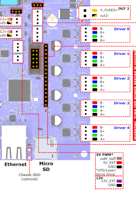
PWM Input + > VFD(out6_buff) pin
Power Supply + > 12v+ next to VFD pins
Power Supply - > 12v- next to VFD pins
Voltage output - (GND) goes to ACM
Voltage output + (AO) goes to VI(I've also tried AI)My config is
M950 R0 C"0.vfd+0.io4.out" Q3000 L24000 ; create spindle #0 connected to vfd pin and 24k rpm at full PWM M563 P1 S"Spindle" R0 ; create tool #1 with spindle 0 M453 ; set cnc mode M568 P1 F0 T1 M3 T1 S0 M5 -
@dhusolo where are you getting the 12V power from? It should be an isolated supply. Alternatively, use the 10V that the VFD provides for the pot.
Duet WiFi hardware designer and firmware engineer
Please do not ask me for Duet support via PM or email, use the forum
http://www.escher3d.com, https://miscsolutions.wordpress.com -
@dc42 12v power is coming from the 12v pins next to the VFD header.
-
@dc42 I confirmed the wiring is correct. I tested the voltage output at the PWM+/- pins and I can see the voltage changing when I adjust the speed in DWC.
This is the wiring
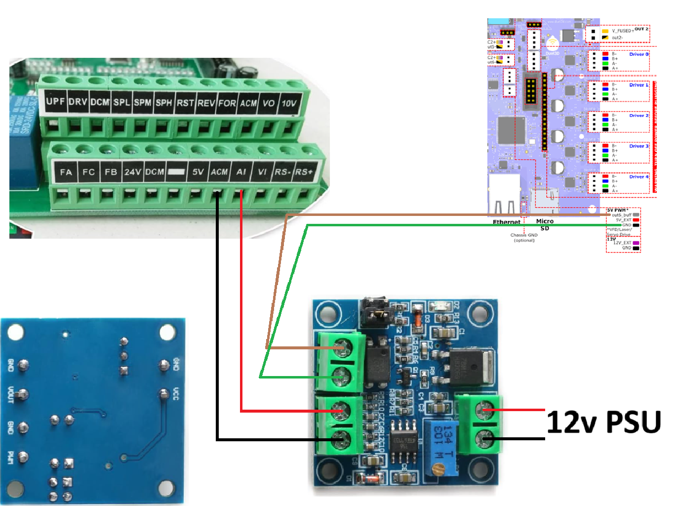
I have a relay connected to io4.out that shorts DCM to FOR when the spindle is turned on.
M950 R0 C"0.vfd+0.io4.out" Q3000 L24000                   ; create spindle #0 connected to vfd pin and 24k rpm at full PWM
M563 P1 S"Spindle" R0                                ; create tool #1 with spindle 0
M453                                        ; set cnc mode
M568 P1 F0                                  ; set initial tool #0 active and standby temperatures to 0C
T1                                          ; select tool 1
M3 T1 S0
M5
I know this is working because when I turn the spindle I can hear the relay clicking and the numbers and the FOR LED on the VFD LCD go solid.
The jumper was moved from J2 to J1. I have the VFD configured for:
PD001 = 1
PD002 = 2
PD070 = 0 -
@dhusolo unfortunately you've purchased the non-isolated version of the converter. See https://docs.duet3d.com/en/User_manual/Machine_configuration/Configuration_CNC#connecting-a-spindle. I don't know whether your VFD will work using an external 12V supply, or whether you have you use the 10V output provided by the VFD. Do not try to feed the 10V output to that converter, it's not safe due to the lack of isolation.
You could try connecting a potentiometer to the 10V output of the VFD and the speed input, to check that the VFD is configured correctly to be controlled from that input.
Duet WiFi hardware designer and firmware engineer
Please do not ask me for Duet support via PM or email, use the forum
http://www.escher3d.com, https://miscsolutions.wordpress.com -
@dc42 damn I'm an idiot. I see that now. I had some of those laying around and didn't realize those were the ones not to use. I'll have to order more green converter boards and see if I can get those to work.
I do have 1 of these 3.3v boards. https://www.amazon.com/dp/B08CRKRBX4?ref=ppx_yo2ov_dt_b_fed_asin_title
But would that work with a duet 3 mini? -
@dhusolo yes that should work.