HY VFD controlled by Duet 3 Mini
-
I have my 110v 2.2kw liquid cooled spindle working. I've got the pump wired to the VFD so when the spindle is running the pump is running. I've been searching the forums for a few days and I can't seem to find anything clear that I need to do for my setup.
I can control the RPM through the dial on the front of the VFD. However I'd like full control through DWC as in being able to use start, stop and change RPMs.
I've seen posts that say since I have a duet 3 mini, using the VFD pins all I have to do is connect:
DCM to GND to ground the VFD and the Duet 3 mini
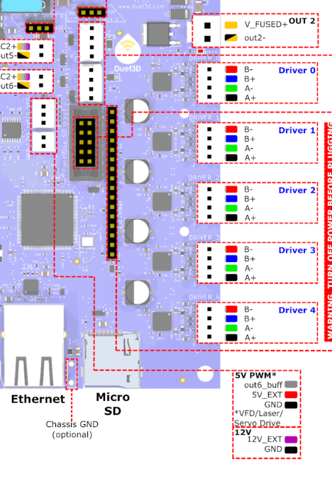
FOR to out6 on the Duet 3 mini to control RPM
I also have a frequency to voltage converter like this one.

So my question is, what's the correct way to do this so I have full control over the spindle through DWC?
-
@dhusolo can you provide a link to the manual for the VFD?
Duet WiFi hardware designer and firmware engineer
Please do not ask me for Duet support via PM or email, use the forum
http://www.escher3d.com, https://miscsolutions.wordpress.com -
-
@dc42 From what I can see it's the HY02D211B VFD. I've got it kind of working. I can control the speed from S6000 to S7000 but it'll max out at 7000, even if I enter s24000.
RRF version 3.5.4
Wifi Server 2.2.0
DWC 3.5.4I've got a jumper wire in between DCM and FOR on the VFD
Out6_buff/VFD goes to pulse input +
and VFD GND goes to pulse input -
This is the one I'm using link text; Configuration file for Duet WiFi (firmware version 3.4.6) ; executed by the firmware on start-up ; ; generated by RepRapFirmware Configuration Tool v3.4.6 on Wed Oct 10 2023 (Central Standard Time) ; General preferences M552 S1 ; enable wifi G90 ; send absolute coordinates... M83 ; ...but relative extruder moves M550 P"CNC" ; set printer name M453 ; configure CNC mode ; Kinematics M669 K0 ; configure Cartesian kinematics ; Drives M569 P0.0 S0 ; physical drive 0.0 goes forwards M569 P0.1 S1 ; physical drive 0.1 goes backwards M569 P0.2 S0 ; physical drive 0.2 goes backwards M584 X0 Y1 Z2 ; set drive mapping M350 X16 Y16 Z16 I1 ; configure microstepping with interpolation M92 X800.00 Y800.00 Z400.00 ; set steps per mm M566 X500.00 Y500.00 Z200.00 ; set maximum instantaneous speed changes (mm/min) M203 X1500.00 Y1500.00 Z2000.00 ; set maximum speeds (mm/min) M201 X1000.00 Y1000.00 Z1500.00 ; set accelerations (mm/s^2) M906 X1800 Y1800 Z1700 I10 ; set motor currents (mA) and motor idle factor in per cent M84 S100 ; Set idle timeout M204 P1500 T3000 ; Axis Limits M208 X0 Y0 Z0 S1 ; set axis minima M208 X316 Y200 Z130 S0 ; set axis maxima ; Endstops M574 X1 S1 P"!0.io3.in" ; configure active-high endstop for low end on X via pin M574 Y1 S1 P"0.io5.in" ; configure active-high endstop for low end on Y via pin M574 Z2 S1 P"!0.io6.in" ; configure active-high endstop for high end on Z via pin ; Fans M950 F0 C"0.out5" Q200 ; create fan 0 on pin out9 and set its frequency M106 P0 C"Board Fan1" ; set fan 0 value. Thermostatic control is turned off ; Spindle Control M950 R0 C"0.out6" Q70 L6000:24000 ; configure spindle #0 M950 P1 C"0.out3" Q500 M42 P1 S0 M950 P2 C"0.out4" Q500 M42 P2 S0 ; Tools M563 R0 P0 S"Spindle" ; create tool #0 M453 M568 P0 F0 ; set initial tool #0 active and standby temperatures to 0C G10 P0 X0 Y0 U0 Z0 ; set tool 0 axis offsets G10 P0 R0 S0 ; set initial tool 0 active and standby temperatures to 0C ; Mist Control ;M950 F0 C"0.out6" Q20000 ; create fan 0 on pin out9 and set its frequency ;M106 P0 C"Mist Control" S0 L0.15 X0.85 H-1 ; set fan 0 value. Thermostatic control is turned off ; Miscellaneous M564 S0 H0 ;Allow movement without homing (without axis maxima) ;T0 ; select first tool M575 P1 S1 B57600 ; Custom settings are not defined -
Any help would be greatly appreciated
-
@dhusolo you have a frequency to voltage converter, however what you need to interface the Duet spindle control to a VFD with 0-10V input is a PWM to voltage converter. See https://docs.duet3d.com/en/User_manual/Machine_configuration/Configuration_CNC#connecting-a-spindle.
Note, when fed from the 10V supply on the VFD these devices can't supply as much as 10V output, so the full spindle speed is not available.
With the frequency to PWM converter that you have, you would need to adjust the Q parameter in the M950 command that set up the port in order to vary the speed.
In future we expect to support control of spindles via Modbus RTU. If your VFD supports the Modbus commands described in the manual you linked to then control over Modbus may be possible in future.
Duet WiFi hardware designer and firmware engineer
Please do not ask me for Duet support via PM or email, use the forum
http://www.escher3d.com, https://miscsolutions.wordpress.com -
@dc42 You sir are correct. I did get the wrong board. I installed an actual PWM to Voltage converter and wired it up. This is the one I'm using now
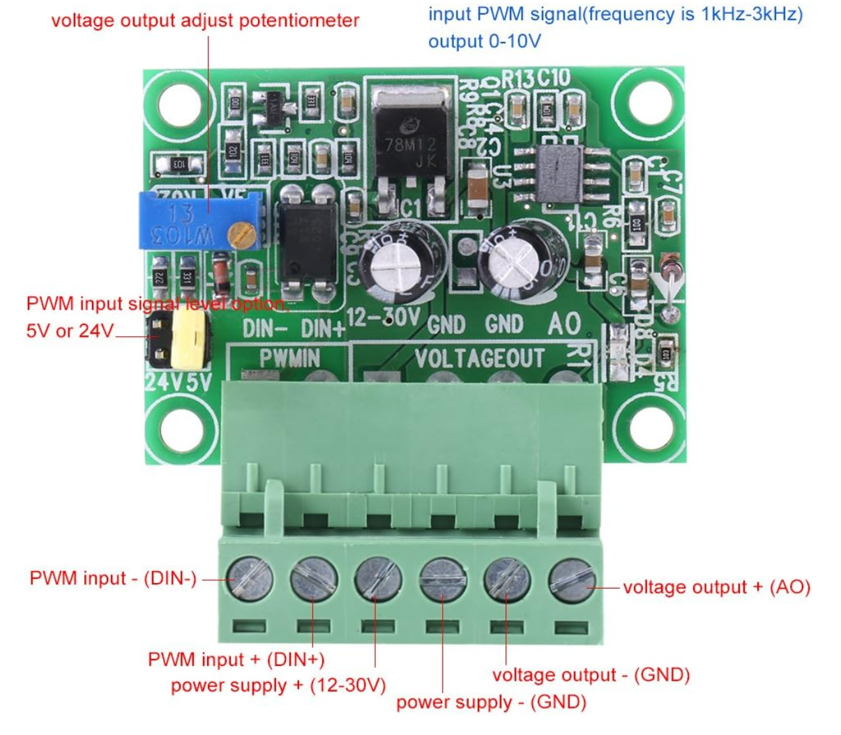
Voltage output - (GND) goes to ACM
Voltage output + (AO) goes to VI(I've also tried AI)I have a relay connected
NO > DCM
COM > FOR
Right now I'm switching it with a macro but eventually I'll get it configured to automatically switch when the drive is working correctly. I know the relay is working because when I switch it on the FOR LED on the VFD goes to solid.
I set:
PD001 = 1
PD002 = 1
PD070 = 0
I've moved the jumper to J1 enabling external potentiometer. I've tested the AO and GND and I am getting about 4.8v at 12k RPMs. But the VFD isn't recognizing the signal from the PWM converter -
@dhusolo how have you connected the converter to the VFD?
Duet WiFi hardware designer and firmware engineer
Please do not ask me for Duet support via PM or email, use the forum
http://www.escher3d.com, https://miscsolutions.wordpress.com -
@dc42 Yes I have. The connections are
PWM Input - > VFD GND Pin
PWM Input + > VFD(out6_buff) pin
Power Supply + > 12v+ next to VFD pins
Power Supply - > 12v- next to VFD pins
Voltage output - (GND) goes to ACM
Voltage output + (AO) goes to VI(I've also tried AI)My config is
M950 R0 C"0.vfd+0.io4.out" Q3000 L24000 ; create spindle #0 connected to vfd pin and 24k rpm at full PWM M563 P1 S"Spindle" R0 ; create tool #1 with spindle 0 M453 ; set cnc mode M568 P1 F0 T1 M3 T1 S0 M5 -
@dhusolo where are you getting the 12V power from? It should be an isolated supply. Alternatively, use the 10V that the VFD provides for the pot.
Duet WiFi hardware designer and firmware engineer
Please do not ask me for Duet support via PM or email, use the forum
http://www.escher3d.com, https://miscsolutions.wordpress.com -
@dc42 12v power is coming from the 12v pins next to the VFD header.
-
@dc42 I confirmed the wiring is correct. I tested the voltage output at the PWM+/- pins and I can see the voltage changing when I adjust the speed in DWC.
This is the wiring
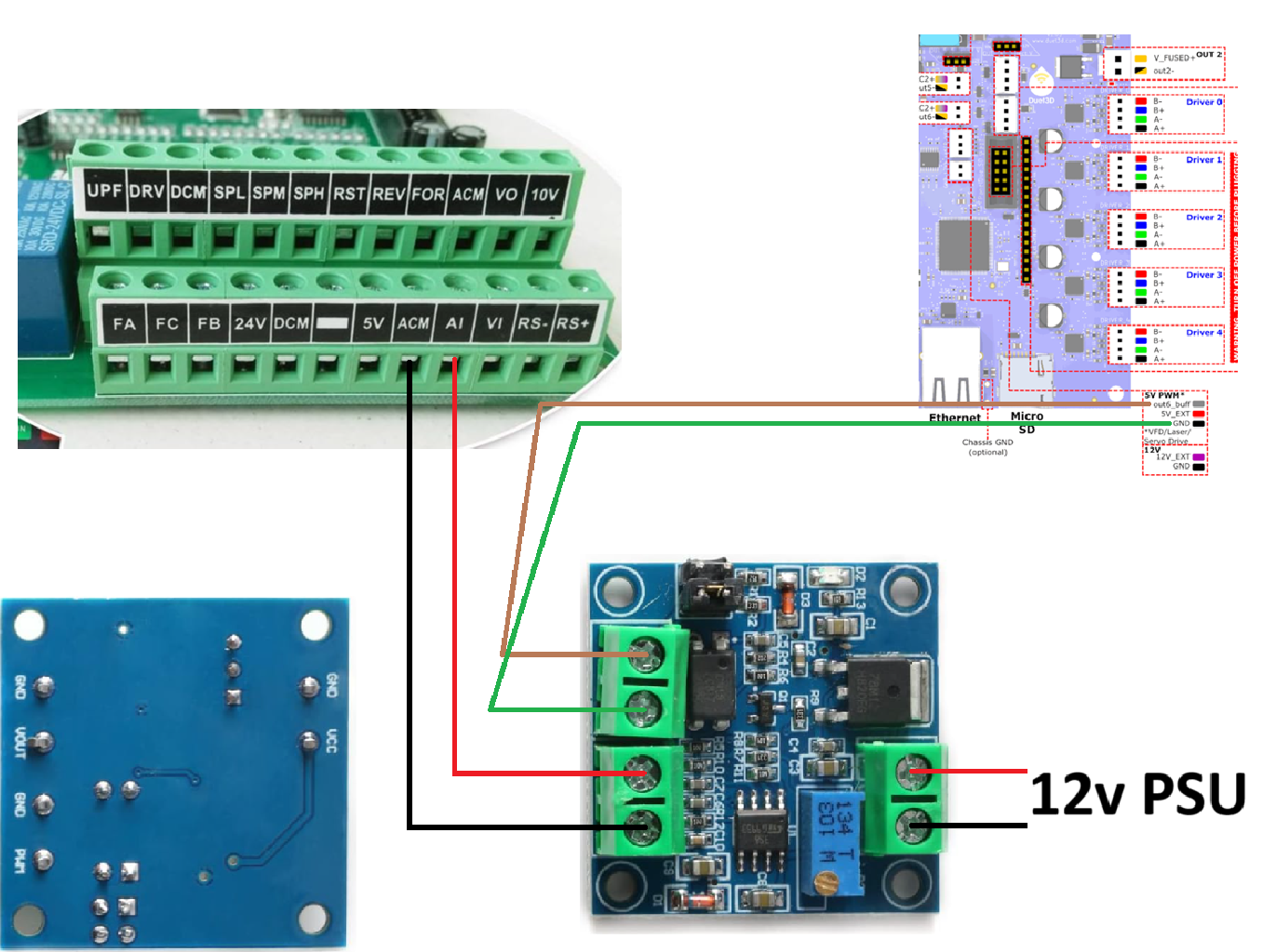
I have a relay connected to io4.out that shorts DCM to FOR when the spindle is turned on.
M950 R0 C"0.vfd+0.io4.out" Q3000 L24000                   ; create spindle #0 connected to vfd pin and 24k rpm at full PWM
M563 P1 S"Spindle" R0                                ; create tool #1 with spindle 0
M453                                        ; set cnc mode
M568 P1 F0                                  ; set initial tool #0 active and standby temperatures to 0C
T1                                          ; select tool 1
M3 T1 S0
M5
I know this is working because when I turn the spindle I can hear the relay clicking and the numbers and the FOR LED on the VFD LCD go solid.
The jumper was moved from J2 to J1. I have the VFD configured for:
PD001 = 1
PD002 = 2
PD070 = 0 -
@dhusolo unfortunately you've purchased the non-isolated version of the converter. See https://docs.duet3d.com/en/User_manual/Machine_configuration/Configuration_CNC#connecting-a-spindle. I don't know whether your VFD will work using an external 12V supply, or whether you have you use the 10V output provided by the VFD. Do not try to feed the 10V output to that converter, it's not safe due to the lack of isolation.
You could try connecting a potentiometer to the 10V output of the VFD and the speed input, to check that the VFD is configured correctly to be controlled from that input.
Duet WiFi hardware designer and firmware engineer
Please do not ask me for Duet support via PM or email, use the forum
http://www.escher3d.com, https://miscsolutions.wordpress.com -
@dc42 damn I'm an idiot. I see that now. I had some of those laying around and didn't realize those were the ones not to use. I'll have to order more green converter boards and see if I can get those to work.
I do have 1 of these 3.3v boards. https://www.amazon.com/dp/B08CRKRBX4?ref=ppx_yo2ov_dt_b_fed_asin_title
But would that work with a duet 3 mini? -
@dhusolo yes that should work.
-
 undefined dhusolo referenced this topic