Problem with external stepper drivers
-
You have the driver numbers as 0, 1, 2 in your first three M569 commands, so the T2 parameter is being applied to the internal drivers, not the external drivers. Your M584 command maps XYZ to drivers 7, 6 and 5. So the P parameters in those M569 commands need to be 5, 6 and 7 not 0, 1 and 2.
-
Tested and works!!!
Two questions:- My correct value is supposed than is T2.5? or biggest?
- Is working…. Taa:bb:cc:dd?? (you say: planned for a future firmware version)
-
One thing….
Axis X and Y works perfect, but Z not.
Axi Z have same stepper driver but.
My table is moved for 4 stepper, each stepper use one driver.
The four drivers is connected to E4 output PUL/DIR.
Perhaps is for this? -
Your drivers require a 5us setup time from DIR changing to the leading edge of STEP, so it would be best to use T5 at present.
The Taa:bb:cc:dd syntax is implemented in firmware 1.21RC5 which I hope to release tomorrow, perhaps even tonight. Then you should be able to use T2.5:2.5:5:0.
-
You are true, tested with 5 and is ok, tested with 10 and is ok.
What will be the difference between use 5 or 10?Thanks for everything.
-
The higher the T value you use, the lower the maximum step rate will be and the more CPU time it will use in generating step pulses. This may affect the maximum microstepping that you can set those drivers to.
-
Only want question more (sorry but this discuss is really interesting….)
-What Steps/rev you advise? 1600-3200... or that? -
3200 or 6400 would be typical values. The limiting factor is the step pulse rate at the highest speed that you want the motors to move.
-
With the new RC5 is necessary totally configure the M569,
so the correct is T2.5:2.5:5:0? (like you say in the old post)Minimum driver step pulse width: 2.5
Step pulse interval: 2.5
Direction setup time: 5
Direction hold time: 0Regard to the draw of my external stepper driver:
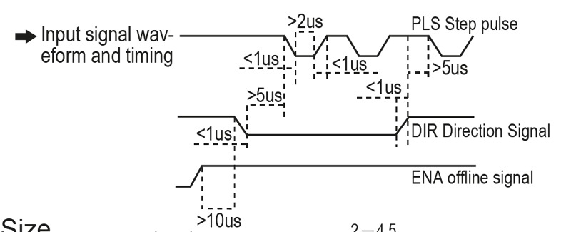
???
I think than the correct is:
Minimum driver step pulse width: 2
Step pulse interval: 5
Direction setup time: 1
Direction hold time: 1
T2:5:1:1 -
That diagram doesn't give the minimum step interval, so you need to work it out from the maximum step rate quoted on the data sheet. The second T parameter is the minimum interval between the end of one step pulse and the start of the next.
-
So, You advise me use this:
T2.5:2.5:5:0Minimum driver step pulse width: 2.5
Step pulse interval: 2.5
Direction setup time: 5
Direction hold time: 0??
-
If the maximum step pulse rate is 200kHz, then yes.