Duet3D Logo Duet3D
    • Tags
    • Documentation
    • Order
    • Register
    • Login

    New board faults

    Scheduled Pinned Locked Moved
    Duet Hardware and wiring
    3
    9
    1.5k
    Loading More Posts
    • Oldest to Newest
    • Newest to Oldest
    • Most Votes
    Reply
    • Reply as topic
    Log in to reply
    This topic has been deleted. Only users with topic management privileges can see it.
    • micktolundefined
      micktol
      last edited by micktol

      I have just received a duet ethernet board, before doing anything I checked the soldering etc.
      There are 3 faults!

      Capacitor c111 is soldered between one of its connections and one of the resistor next to it.
      Capacitor c104 is only soldered on 1 side as it is misplaced.
      There is a large amount of white paste around the area of c53 c60.

      Is this a problem?

      0_1527685359359_DSC_3572.JPG

      0_1527685379473_DSC_3571.JPG

      0_1527687534880_DSC_3573.JPG

      1 Reply Last reply Reply Quote 0
      • T3P3Tonyundefined
        T3P3Tony administrators
        last edited by

        @micktol That is not great 😕

        I am very sorry you have received a board in this state. Please can you contact your supplier (or me by email if you bought it directly from us) and arrange a warranty replacement. you can reference this thread.

        www.duet3d.com

        1 Reply Last reply Reply Quote 0
        • wilrikerundefined
          wilriker
          last edited by

          @T3P3Tony It never occurred to me to doubt the quality of the board in the first place.

          Now I have looked at it and I found a couple of solder pads where no components are actually soldered to but I have no idea where to check whether this is intentionally or a fault (certainly I had no issues with my board so far, so at least I guess these are missing by definition).
          Instead of spamming this thread could you please tell me where I can find if and what components are supposed to be missing on a Duet Wifi that have declaration on silk screen and solder pads prepared?

          Manuel
          Duet 3 6HC (v0.6) with RPi 4B on a custom Cartesian
          with probably always latest firmware/DWC (incl. betas or self-compiled)
          My Tool Collection

          T3P3Tonyundefined 1 Reply Last reply Reply Quote 0
          • T3P3Tonyundefined
            T3P3Tony administrators @wilriker
            last edited by

            @wilriker There are a number of DNP 0603 resistors, they are annotated on the schematic:
            https://github.com/T3P3/Duet/blob/master/Duet2/Duet2v1.03/Duet2_Schematic_v1.03.pdf

            www.duet3d.com

            wilrikerundefined 1 Reply Last reply Reply Quote 0
            • wilrikerundefined
              wilriker @T3P3Tony
              last edited by

              @t3p3tony Thanks! I will take my printer apart tomorrow (this is a planned activity 😉 ) and as part of that I will closely examine the board and compare it to the documentation regarding DNP. I do not expect anything unusual as my board worked flawlessly as long as I have it (about a month) but this thread now got me started. 😁

              Manuel
              Duet 3 6HC (v0.6) with RPi 4B on a custom Cartesian
              with probably always latest firmware/DWC (incl. betas or self-compiled)
              My Tool Collection

              T3P3Tonyundefined 1 Reply Last reply Reply Quote 0
              • T3P3Tonyundefined
                T3P3Tony administrators @wilriker
                last edited by

                @wilriker a quick summary to save you time:

                R73, R74,R75,R76 close to the SD card, along with the JTAG port and associated resistors, R35,R49,R52
                0_1527711090805_5455e7de-3412-4c80-9e6c-d381c413cf13-image.png
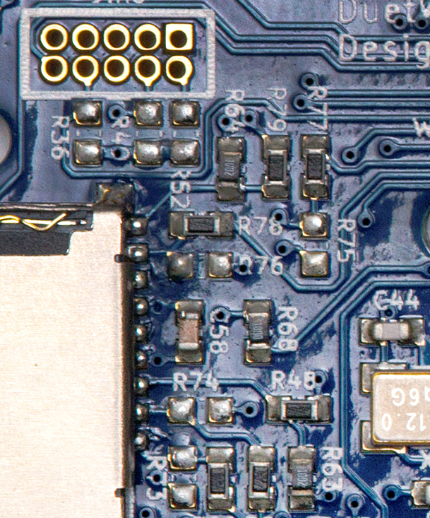
                these can all be seen in the image above

                R82 and C83 around the ESP
                0_1527711239165_fa8516c1-ee24-4506-a69d-2afedf0e091e-image.png

                and C95 next to the 3.3V LDO:
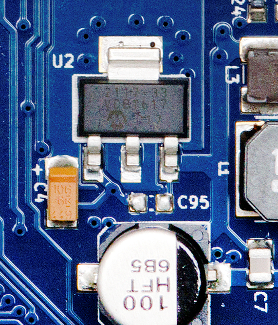
                0_1527711346248_03f9d793-e545-4912-add0-1d8b1a9cde37-image.png

                HTH

                www.duet3d.com

                wilrikerundefined 1 Reply Last reply Reply Quote 0
                • wilrikerundefined
                  wilriker @T3P3Tony
                  last edited by wilriker

                  @t3p3tony Thanks, that made things a lot easier. 🙂 I can at least confirm now that nothing else is missing.

                  Only thing I found is that the large extension header and the VIN terminal block both are not sitting 100% flat on the PCB. This has no functional issues AFAICT but is something the assembling should be advised to look after.

                  I will attach photos in a moment.

                  0_1527921382847_VIN.jpg

                  0_1527921837440_Expansion.jpg

                  All pins in both cases are soldered correctly, so again, I see no functional issues here.

                  Manuel
                  Duet 3 6HC (v0.6) with RPi 4B on a custom Cartesian
                  with probably always latest firmware/DWC (incl. betas or self-compiled)
                  My Tool Collection

                  1 Reply Last reply Reply Quote 0
                  • micktolundefined
                    micktol
                    last edited by micktol

                    I have received the replacement board and c111 is misplaced as before, quality control?

                    What NOW?

                    0_1528111397292_DSC_3580.JPG

                    T3P3Tonyundefined 1 Reply Last reply Reply Quote 0
                    • T3P3Tonyundefined
                      T3P3Tony administrators @micktol
                      last edited by

                      @micktol I have replied to your new thread.

                      www.duet3d.com

                      1 Reply Last reply Reply Quote 0
                      • First post
                        Last post
                      Unless otherwise noted, all forum content is licensed under CC-BY-SA