Mesh grid results
-
I've just ran the mesh grid compensation on my delta printer, and I need help trying to understand the results. What I gather from the map is that the high spots correspond with the location of the towers and opposite of the towers there is a low spot. Any idea's on what causes these results?

-
before doing bed probing are you running delta calibration? what results are you getting from that? https://duet3d.dozuki.com/Wiki/Calibrating_a_delta_printer#Section_Auto_calibration
-
Also how many factors are you using the calibrate (The Sx at the end of the last G30 line in your BED.g?
-
@t3p3tony Yes I am running normal delta calibration before, twice actually (though results are virtually identical). Deviation after calibration is around 0.1mm.
@Dougal1957 I use 8 factor calibration.
-
For what it's worth, I get something similar.
I use Haydn's magnetic joints with precisely measured lengths. I'm wondering if it could be down to the belts not being 100 parallel to the rails.
adavidm

-
@nxt-1 said in Mesh grid results:
@t3p3tony Yes I am running normal delta calibration before, twice actually (though results are virtually identical). Deviation after calibration is around 0.1mm.
@Dougal1957 I use 8 factor calibration.
0.1mm is not bad but of the same order as the oddity on the bed mesh. I am going to try this on mine (I don't generally use the mesh bed compensation on my deltas as the glass print surface is pretty flat).
-
@t3p3tony said in Mesh grid results:
0.1mm is not bad but of the same order as the oddity on the bed mesh. I am going to try this on mine (I don't generally use the mesh bed compensation on my deltas as the glass print surface is pretty flat).
0.1mm is indeed not bad but if you loot at it compared to the layer thickness it is quite a bit actually. I am only just looking into mesh bed compensation (I print on glass too).
The main reason I posted here is because there is a noticeable pattern, that must have some cause that I would like to know")
-
Not sure what's wrong here, used to be flat but re-run it today and it looks like a ploughed field with furrows? Cant see anything mechanically wrong, using smart effector and Haydn rods. Any ideas anyone?

-
@pilotltd said in Mesh grid results:
Not sure what's wrong here, used to be flat but re-run it today and it looks like a ploughed field with furrows? Cant see anything mechanically wrong, using smart effector and Haydn rods. Any ideas anyone?
This issue seems not related, may I kindly ask to keep this thread relevant and start your own thread.
-
@nxt-1 Sorry but seems relevant to me ? I'm trying to understand my results just like you.
-
Two thoughts:
-
Check very carefully for bits of filament at the probe spots (left from prior probes). Check with your fingernails.
-
Run mesh probing at least twice, if not three times, and compare the results.
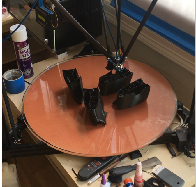
Here is mine at the moment, and a shot of the bed itself (24", 608mm, supported at six points only, no clamps, and heater is stuck directly to the bottom of the glass, no aluminum). Print in the shot is wing sections for a flying radio-control F4U Corsair from 3dlabprints.com.
Like you guys, I don't know exactly what should be acceptable or not... I can tell you reflections from the glass are not distorted, and that it prints fine.

-