Relay to turn PSU's on/off
-
So reading through existing posts and not wanting to be a necromancer I'm giving this a shot.
TL:DR Relay via GPIO to turn on/off PSU's yay/nay?
I'm converting from ramps/mega to a Maestro. And two things I now know I'll be missing is octolapse and psucontrol. Or octoprint in general I guess

If I connect everything as I've done on my ramps, 12v in, heatbed to mosfet>24v both PSU's will run from the same outlet through a relay.
Can I then grab the GPIO's on the Meastro?
And then inject M80/81 from the DWC ?
I'm thinking something like this:expansion1(5v) > JD-VCC
expansion2(GND) > GND
expansion4(exp_0) > to what ever relay port i'm running.
expansion10(3v3) > VCCBut how do I ensure that the board is turned on constantly ?
-Does it get enough juice from the USB inlet ?But not being super familiar with both RRF/DWC and how M80 actually works, I'm not sure how M80/81 knows that I want to issue this on exp4
Or I should only look half on the GPIO and use the External 5v under the Z steppers?
I guess by looking at it I have what I need. 5v, GND and PS_ON ( is this where the m80 is directed to ?)
Timelapse is somewhat doable but I'll still need the Pi to run the webcam.
-But that's another storyCheers!
-
Hi @fizban,
That username sure takes me a long way back
")
There are many questions intermingled in your post and I'm not sure how much I can actually be of help - especially since I'm working with the DuetWifi and you're going to be using the Maestro, so there may be differences I'm not aware of - but if I understand correctly what you're trying to achieve, then I tackled the same challenge a while back and the implementation works like a charm so if you're interested have a look at this thread (particularly the first post where all the schematics and relevant data are linked to - might be a bit difficult to see at first glance).
Hopefully, this would give you a good reference/starting-point for creating your own solution.
If you need clarifications and/or if you (or anyone else) is interested in the PCB design or anything else related to this, give me a shout out and I'll post them up too.
Best of luck!
SnowCrash -
Looking at the Wiring Diagram of the Maestro, it is very similar to the Wifi and Ethernet (https://duet3d.dozuki.com/Wiki/Duet_2_Maestro_Wiring_Diagram).
If you look at the diagram, on the right hand side, there is a 3-pin connector with PS_ON (which you mentioned; there is the 5V[external 5V], PS_ON and GND) and here is how it works:
- For the Duet to do anything, it needs 5V. This can be given by any of the following ways: USB connector; 5V[ext] or Vin (given at least 12V). Using the Vin, an internal regulator will provide the 5V from which the Duet will run (and regulate its 3.3V used for logic). When using the 5V[ext] you need to make sure the 5V[etx] jumper is in place (you get the jumper from the "Int 5V En" header) - this will put the integrated 5V regulator into a disabled state since 2 regulators can't share an output.
- The M80 and M81 Gcodes control the PS_ON pin. Now it should be noted that the pin is in high-impedance state by default, and actively pulled LOW when the PS_ON output is active.
There are various ways you can use this to control a power supply:
- ATX Power supplies. Connect the always on 5V wire to the ETX 5V pin (and ensure the jumper is set to use this); connect a Ground to the GND pin and also connect the PS_ON pin with the Power On wire (this is the intended use for the PS_ON pin).
- Connect the Duet with separate 5V power. Connect a Relay (with reverse bias diode) between a 5V source and the PS_ON pin. When not active, no power flow through the relay.
On my 3d printer I used a method similar to the 2nd option, with a few exceptions. I did not use a separate power supply, instead I have a momentary switch which bypass the relay (my relay is a 24V relay getting the 24V directly from the PSU, with the diode as protection). So to turn on, I press the switch, which provides power to the PSU, which generates the 24V Vin, which is regulated to 5V and 3.3V for the Duet which immediately engages the relay, allowing me to release the button. I have a macro to shut the printer down, and on the DWC, I can select the option to "Enable Auto Sleep" which will also shut it down after a print is done.
If you want to map it to a different pin, you will need to modify the firmware. While that is possible, generally it is not required. With RRF most machines can be configured without touching the source code.
-
@snowcrash Glad I could wake up some memories! =D Hes the man!
Any particular reason you used a SSR and not just a
I'm pretty sure this should do all that I require
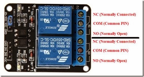
GND to GND
5v to VCC
PS_ON to IN1 or IN2And then I'll run the 230v through NC and NO just like I do on my raspi setup
If I need the jumper or not I'm not entirely sure, cause I run both 5v and 3v3 on the raspi@Jacotheron I like the idea, but I want to turn it on/off by software only
Theres always power flowing to the relay via a switch. But it wont reach the printer till I do M80
That's the flexibility I have now than I can control everything from work or just remotely.")
-
@fizban said in Relay to turn PSU's on/off:
Any particular reason you used a SSR and not just a
As this part of the machine deals with very high voltages (and currents), I wanted the best quality and long-term reliability, as well as no reverse current issues. A good SSR from a reputable manufacturer gives you just that. For me, it was worth the steep cost, though different people work with different budgets and have different views of cost-value of course.
I'm not familiar with the specific module in the picture, but I see no reason why it wouldn't be suitable, at least in principle. I'll leave it to others who know more about it to comment on the hookup etc. as this is very sensitive stuff so you want to keep as safe as you can with it!
-
@snowcrash Oh I know, but it's lasted a while now on the raspi. Its rated for 10A/250v so 2000w would be plenty safe
I'll start by hooking up the board and run a test print.
I'm not at all familiar with RRF so it's a new world. After that I'll get the relay sorted.