Duet3D Logo Duet3D
    • Tags
    • Documentation
    • Order
    • Register
    • Login
    1. Home
    2. SnowCrash
    • Profile
    • Following 0
    • Followers 0
    • Topics 35
    • Posts 203
    • Best 18
    • Controversial 0
    • Groups 0

    SnowCrash

    @SnowCrash

    23
    Reputation
    21
    Profile views
    203
    Posts
    0
    Followers
    0
    Following
    Joined Last Online

    SnowCrash Unfollow Follow

    Best posts made by SnowCrash

    • FSR Controller Module for Auto Bed Leveling

      Hi,

      I wanted to share the FSR controller module for auto bed-leveling that I've designed to work specifically (but not exclusively) with the Duet.


      Background

      The initial inspiration for this mini-project came from JohnSL's excellent open-source project for this application.

      At first I thought I'd experiment with the ready-made kit that's based on John's work and sold online commercially, but given the price-tag ($34.95 before shipping), I decided I'd rather make my own module with the exact specifications I'm looking for.

      Both John's module and my own are designed to run 3 x FSRs (Force Sensitive Resistors) simultaneously, like the one shown below:

      0_1531608566496_fsr_controller_sensor.png

      I got mine at RapidOnline, but they are readily available from numerous other suppliers, either with long or short leads.

      The PCB dimensions of John's module and the one I made are also similar (though mine is slightly bigger), but that's where the similarities end as both the hardware and firmware are fundamentally different.


      Design Considerations

      I wanted to create a module that:

      • Can be seamlessly integrated with my Duet, but can also run in standalone mode (for testing and/or use in other, non-Duet machines).

      • Runs as fast and reliably as possible.

      • Has a minimal footprint.

      • Offers a convenient and easily accessible user interface, including onboard LEDs for indicating the initialization process and real-time sensor triggering.

      • Is able to automatically and quickly establish a baseline at startup against which to measure subsequent bed probes during the bed-leveling procedure.

      • Incorporates an adjustment mechanism for controlling the sensors' sensitivity level.

      • Can be reset manually to re-establish the measuring baseline.

      • Can be turned on (for bed-probing) or off (after the procedure is done).

      • Has an ICSP capability for bug fixes and/or future firmware updates.

      • Facilitates expandability to 6 x FSRs in case I'd like to go down that route at some point.


      PCB

      After some reading, head-scratching, and playing around with the PCB editor, I came up with the following design that covers all of the above:

      0_1531607095362_fsr_controller_pcb_top.png

      0_1531607108209_fsr_controller_pcb_bottom.png

      0_1531606826250_fsr_controller_pcb_dimensions.png

      0_1531615193133_fsr_controller_module.png


      Hardware Specs

      • 5V Supply Voltage (I considered going with 3.3V like the Duet's logic, but in the end decided against it because I wanted the microcontroller to run at max speed)

      • Atmega328P-AU (smd version) @ 16MHz with an external crystal (for accurate timing)

      • ICSP header (for firmware updates/bug fixes)

      • Reset Button (for re-establishing the baseline for trigger measurements)

      • 10K Trimmer (for manual sensitivity adjustment)

      • 4 x LED indicators (1 x for power [green], and 3 x for each of the sensors [amber])

      • Signal Output - an Active-Low Open-Collector Combined signal for the 3 sensors (the signal is 5V, but is nevertheless compatible with the Duet interface via an onboard reversed diode).

      • An inductor/capacitor circuit for improved ADC readings of the sensors.

      • Control Input - for turning the module on/off via one of the Duet's I/O pins (see the Schematics pdf attached below for an example of how to turn the module on/off with the Duet).

      • Control Jumper - normally remains open, but can be closed to keep the module permanently on (for independent testing and/or use in other machines).

      • Pull-up resistor Jumper - normally remains open (as the Duet already has built-in pull-up resistors on its signal input pins), but can be closed for independent testing and/or use in other machines (essentially, closing this jumper converts the signal from open-collector type to a regular 5V/GND signal, but note that the signal is still Active-Low, i.e. 5V means none of the sensors is triggered, and GND means one or more are triggered)

      • Reversed Polarity Protection for the module's supply lines (by means of a P-channel mosfet).

      • The PCB itself was designed with the free version of Eagle and manufactured by OSHPark.


      Firmware Specs

      • Firmware was written in Arduino-Style C using the free Arduino IDE.

      • I've used the 'nano' bootloader - rather than the conventional bootloader for the Atmega328P - because the smd version of this chip has more I/O pins and thus requires an appropriate bootloader to run properly.

      • When turned on, the module runs a quick calibration procedure (about 2 seconds), in which it samples each of the sensors and establishes a 'baseline' average against which to check sensor triggering at runtime (this is a crucial feature for preventing false readings from the sensors as there will always be some initial pressure present (from the build-plate's weight if nothing else).

      • The initialization (or calibration) process is visually indicated by all amber sensor LEDs flashing 4 times, after which the module enters runtime mode.

      • During runtime, the output signal is pulled low and the relevant amber LED lights up whenever one of the sensors is triggered (two or more sensors can be triggered simultaneously).

      • If sensor triggering appears to be too sensitive or not sensitive enough, the 10K trimmer can be adjusted and then the reset button clicked so as to re-run the calibration process.


      Open Source Design Files

      Important Disclaimer: I've been working with electronics for a long time, but I am nevertheless a hobbyist and not a professional hardware engineer of any kind. I can therefore give no guaranty about the content of these files, apart from the mere fact that I've built the module and tested it myself. Hence, should you choose to use any of the following materials (or their derivatives), you must also be willing to take full responsibility for doing so.

      fsr controller - schematics (pdf)

      fsr controller - parts (Excel .xlsx)

      fsr controller - firmware (Arduino .ino)

      fsr controller - schematics (Eagle .sch)

      fsr controller - schematics (Eagle .brd)
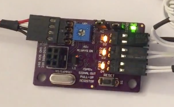

      See It Live!

      Here's a link to a short demonstration of the module in action 🙂

      You'll notice that I click the 'reset' button on the module right at the beginning of the video - this is just to show the initial calibration process and isn't needed for normal operation.

      Also, I haven't had a chance to install the module in my printer yet so there's still a lot of testing and potential firmware/hardware tweaking to be done, but given that many others have successfully implemented similar FSR architectures for bed-leveling (for example, see here), I'm hopeful this particular implementation would work out well too.

      Should there be any interest, I'd be happy to report back on my progress with this, and of course, all comments/suggestions/corrections are always welcome 🙂

      Thanks for reading,
      SnowCrash

      posted in Third-party add-ons force sensitive resistor bed leveling
      SnowCrashundefined
      SnowCrash
    • RE: First-Time Setup - Problem with Connecting to Network

      I wanted to add a postscript to this thread in praise of Duet3D's exceptional customer service.

      Identifying the hardware problem with the controller has taken a bit of time and effort (thanks again Phaedrux & dc42!), but once this was accomplished - and notice that dc42 was responding to my queries over the weekend(!) - the matter was resolved extremely efficiently and quickly.

      I sent the email to Duet3D with the replacement request on Saturday. I got a response first thing Monday morning to let me know that a new board is on the way, and the board itself arrived the very next day!

      Customer service was a major factor in my decision to go with the DuetWifi. As we all know, everybody are great at the point of sale, but very few follow it up later on if/when problems arise. Prior to buying the DuetWifi, I've seen posts from other people commending Duet3D for their customer care, but now I can also vouch for it from my own personal experience. The process was extremely efficient and pain-free. I didn't need to chase anyone or sit and wait till someone got around to sorting it out.

      Well done, Duet3D, and keep it up! you'll certainly gain many more loyal customers like myself! 🙂

      posted in Firmware installation
      SnowCrashundefined
      SnowCrash
    • RE: gcode everywhere... a user friendly approach to config?

      I feel your pain, @biscuitlad, and hope you won't give up on your printer despite all the trails and tribulations you've experienced so far.

      Like you, I've been having some mighty struggles with the g-code-based approach to config.g. It's undoubtably a steep learning curve for anyone not previously familiar with it.

      As you rightly note, the Duet eco-system is very complex and offers multiple configuration possibilities, but to my mind at least, that's actually plus. The problem, of course, is finding the right configuration for the machine at hand...

      I don't know if (or how much) you've tried to get help from other members in this forum, but in case you haven't, I'd certainly recommend trying that.

      On the other hand, if online requests for assistance didn't produce the desired results, perhaps it might be possible to find an experienced Duet user somewhere in your vicinity who might be willing to drop by and get you going on the right track? There are lots of good people on this forum and I'm sure they'd be happy to help if they can.

      One other point I'd make - and I don't know if you'll agree with me on this, but it seems relevant - is that in my view, your case provides yet another example of the need to significantly upgrade the documentation so as to bring it on par with the high level of the Duet's hardware & software. Personally, I think the documentation is lagging way behind atm.

      Don't lose hope, @biscuitlad! Sometimes it's good to just take a step back and let things rest for a while before having another go 🙂

      posted in General Discussion
      SnowCrashundefined
      SnowCrash
    • RE: DuetWifi & PanelDue 10-Pin Ribbon Cable Hookup Clarification

      @t3p3tony said in DuetWifi & PanelDue 10-Pin Ribbon Cable Hookup Clarification:

      @t3p3tony and now its fixed:

      I'm not sure this is the correct place to post this comment, but it's related to previous posts so here goes.

      Having done a lot of work in the past couple of weeks with this excellent pinout diagram, it occurred to me to suggest a tweak that I know would be very helpful to me and hopefully to others as well.

      The connectors on the board are of course keyed, however, the diagram doesn't reflect the keying direction. This means that when making a new cable for one of the connectors, I first refer to the diagram for the order of wires and then need to look at the actual board to check in which direction the connector is keyed.

      On the other hand, had the diagram also included the keying direction of each connector, it would make things much simpler as there wouldn't be a need to check the actual board when making new cables.

      posted in Duet Hardware and wiring
      SnowCrashundefined
      SnowCrash
    • RE: Auto/Manual 'Save Log' and/or 'Export Log'

      Hi @phaedrux, yes, very much so 🙂 Thanks!

      posted in Duet Web Control wishlist
      SnowCrashundefined
      SnowCrash
    • RE: Detect overheated driver

      @dc42 said in Detect overheated driver:

      Unless you are using very old firmware, you will get warning messages in the Console pages of DWC and PanelDue if the drivers overheat. You can also use M305 to set up a virtual heater to monitor them.

      @dc42, could you please give a couple of concrete examples of how to set up a virtual heaters for, say, Driver 0 (X-Motor) and Driver 1 (Y-Motor) using the M305 command so that they could be monitored in DWC?

      I've read and re-read the documentation on this here, but still not sure what the specific parameters ought to be, mainly the 'P' parameter.

      What I find a bit confusing is that in my config.g I have:

      M305 P1 T100000 B3950 C0 R4700 ; Set thermistor + ADC parameters for heater 1;

      But, unless I'm mistaken, that would mean P1 is mapped to the E0 driver which runs my extruder stepper, so I'm not sure how the axis drivers are mapped to the 'P' parameter.

      I'm also not entirely clear what other parameters are needed in this context (if any)?

      Edit: I hope this isn't highjacking your thread, @mperdue . My question seemed directly relevant to your query, but if needed, I'll happily start a new one).

      posted in General Discussion
      SnowCrashundefined
      SnowCrash
    • Maximum Frequency of PWM Fans

      Hi,

      I understand the frequency of the PWM fans can be changed via the F parameter of the M106 command.

      I've seen a comment by @dc42 here suggesting this frequency be set to 25KHz, however, I'd like to know what's the maximum frequency the hardware & firmware allow the user to set?

      Btw, this seems like a good place to offer my 2-cents on this subject. Although I'm a newbie to the DuetWifi, I've been working with PWM fans and pumps for a long time and there are two things I find baffling about the DuetWifi's setup in this context:

      (1) The default frequency for the PWM fan outputs seems to be 500Hz. That may suitable for LEDs, but certainly doesn't even come close to what PWM fans typically need to to work efficiently (and quietly!).

      Although there isn't an agreed industry standard on the suitable frequency for PWM fans, many applications use a 25KHz signal, while the recommended frequency in many of the more reputable sources I came across over the years set the value even higher at 31.5KHz. My experience has been that the latter works very well in most cases.

      On the other hand, a 500Hz frequency will almost invariably drive PWM fans very poorly as indicated by a particularly annoying whining sound most of them would generate at this frequency.

      I therefore think it would be a very good idea to change the default frequency value to something along these lines so that people who aren't aware of this setting would still be operating their PWM fans at a reasonable frequency.

      (2) The DuetWifi has only 2 pins per fan connector, hence no dedicated PWM line. Consequently, I'm assuming the so-called 'PWM control' of the fans via the DuetWifi is achieved by pulsating their input voltage.

      If this is indeed the case, this isn't a great idea. Non-PWM fans aren't designed for this method of operation and operate much better (and quieter) when their speed is varied through voltage control.

      Don't get me wrong, I think PWM is phenomenal and I certainly use it wherever possible. Also, there are ways to implement voltage variation on the basis of a PWM signal, but unless I'm completely off, this isn't how it's implemented in the DuetWifi.

      posted in Duet Hardware and wiring fans pwm control
      SnowCrashundefined
      SnowCrash
    • M558 - What is 'Dive Height'?

      Hi,

      The gcode wiki specifies a 'Dive Height' parameter (Hnnn), but I couldn't find an explanation about what this parameter does or how it works.

      Could anyone please clarify?

      Many thanks,
      SnowCrash

      posted in Tuning and tweaking
      SnowCrashundefined
      SnowCrash
    • RE: Detect overheated driver

      @phaedrux said in Detect overheated driver:

      I believe I recall @dc42 saying previously that the drivers are monitored for a high temp and overtemp, hence the two virtual heaters. The reason for being combined being that they are intended to be used for thermostatic control of a case fan. The hottest driver would trigger the increase in cooling.

      Since the drivers can generally be run passively cooled I don't know the benefit of knowing exactly how hot they are since we can already achieve a cooling strategy with virtual heaters provided.

      As Deckingman said, adding a thermistor would get you the exact temp and associated control.

      Ahh, now the 2 virtual drivers vs 5 physical drivers make more sense - thanks, @Phaedrux! Shame it's not in the wiki...

      Also, as always, you make great points here.

      Nevertheless, I can see at least one advantage to being able to monitor the actual temps (or even just the status, i.e. high-temp and over-temp), which is it provides a way to verify that the temp-control fans are indeed operating as intended. Put a different way, atm how do you know that the fan comes on when it needs to?

      posted in General Discussion
      SnowCrashundefined
      SnowCrash
    • RE: Grounding!

      @dc42 said in Grounding!:

      And yes, stepper motor cases should be grounded, to prevent the buildup of static charge caused by the moving belts.

      I have the printer's metal frame grounded to the mains ground (AC ground), but I was wondering in the context of the above discussion:

      Would it be preferable to ground the motor cases to the negative DC terminal of power supply's (DC ground) or the main's ground (AC ground)? or, perhaps , no difference?

      posted in Duet Hardware and wiring
      SnowCrashundefined
      SnowCrash

    Latest posts made by SnowCrash

    • RE: Laser Filament Monitor 'SW' PCB Pads

      @dc42 said in Laser Filament Monitor 'SW' PCB Pads - Unsolved:

      @snowcrash said in Laser Filament Monitor 'SW' PCB Pads - Unsolved:

      Ok, so... was my original understanding correct? that is, the voltage reading between the 2 pads (High/Low) serves as an indicator for filament present/not-present?

      Our intention is that if you want to add a filament presence switch, you add a switch that shorts those 2 pads together when filament is present.

      To make it easier for us (or anyone else) to prototype new functionality.

      In what why exactly? could you please give an example?

      No, because we haven't used them yet.

      Ok, thanks

      posted in General Discussion
      SnowCrashundefined
      SnowCrash
    • RE: Laser Filament Monitor 'SW' PCB Pads

      @dc42 said in Laser Filament Monitor 'SW' PCB Pads - Unsolved:

      @snowcrash said in Laser Filament Monitor 'SW' PCB Pads - Unsolved:

      If I bridge the SW 'jumper-pads' (J1) - then the Signal Output (i.e. OUT on P1) becomes a binary output, that is, High for 'no filament' & Low for 'filament present' (or, perhaps, vice versa)?

      No. One of the 16 bits in the position report returned to the Duet is the switch status.

      Ok, so... was my original understanding correct? that is, the voltage reading between the 2 pads (High/Low) serves as an indicator for filament present/not-present?

      Also, what is the purpose of the M2 pads (according to the schematics they bridge PA0 & PA1 on the ATtiny)?

      To make it easier for us (or anyone else) to prototype new functionality.

      In what why exactly? could you please give an example?

      posted in General Discussion
      SnowCrashundefined
      SnowCrash
    • RE: Laser Filament Monitor 'SW' PCB Pads

      I had another look at the schematics for the filament sensor and I'd like to know if I got this straight (it seems like my previous understanding of the SW pads' function wasn't right):

      If I bridge the SW 'jumper-pads' (J1) - then the Signal Output (i.e. OUT on P1) becomes a binary output, that is, High for 'no filament' & Low for 'filament present' (or, perhaps, vice versa)?

      Also, what is the purpose of the M2 pads (according to the schematics they bridge PA0 & PA1 on the ATtiny)?

      Thanks.

      posted in General Discussion
      SnowCrashundefined
      SnowCrash
    • RE: Laser Filament Monitor 'SW' PCB Pads

      @dc42 said in Laser Filament Monitor 'SW' PCB Pads & Inner Chamber Color:

      A filament presence switch is a simple switch that tells the sensor whether filament is present or not. So it can tell the Duet instantly when a spool runs out. But it's not really needed, because the end of the filament will pass through the filament monitor, which should detect loss of motion before the end reaches the extruder drive.

      So the voltage across these pads alternates between High & Low on the basis of filament presence regardless of the main signal from the monitor module? does this functionality exist out-of-the-box or are tweaks needed?

      posted in General Discussion
      SnowCrashundefined
      SnowCrash
    • RE: Laser Filament Monitor 'SW' PCB Pads

      @dc42 said in Laser Filament Monitor 'SW' PCB Pads & Inner Chamber Color:

      1. It's for an optional filament presence switch.

      Thanks for the very quick response, @dc42!

      Could you please elaborate on what 'an optional filament presence switch' is and what it does?

      posted in General Discussion
      SnowCrashundefined
      SnowCrash
    • Laser Filament Monitor 'SW' PCB Pads

      Hi,

      I got Duet's newly released laser filament monitor a while back but only now starting to look into hooking it up in my rig & I have the following questions which I'm hoping to get some info on:

      (1) on the sensor's PCB there are a couple of round pads marked 'SW'. Looking at the schematics they seem to me to be intended for connecting an external reset switch - is this correct? and if so, has anyone utilized this feature? How useful is it to have?

      (2) What would be the best background color (if any) for the inner chamber where the sensor's 'camera' chip is located (i.e. where the filament runs and inspected by the chip)? does the color even make a difference in this context?

      Many thanks in advance.
      SnowCrash

      posted in General Discussion laser monitor filament
      SnowCrashundefined
      SnowCrash
    • RE: Help with Steps per mm Calculation

      Thank you, @phaedrux! as always, an excellent comment & very useful info 🙂

      @phaedrux said in Help with Steps per mm Calculation:

      If you're set on using those 12mm pitch lead screws I don't think 533.3 steps per mm will be very detrimental to you. Is that the only pitch option available in that diameter?

      I'm currently undecided as I'm not sure the gains in resolution would be worth the expense.

      As for lead-screws with other pitches, those are the only ones (apart from the 10x25 I have) with a 10mm diameter I could find on Igus. I tried looking in other places, but so far haven't found anything suitable.

      And as I mentioned above, I'd rather stick with the 10mm diameter to avoid the need to replace a whole set of bearings.

      So if anyone has a recommendation for good quality lead-screws at a decent price with 10mm diameter, I'd be very interested to hear it.

      @phaedrux said in Help with Steps per mm Calculation:

      I forgot to address your question about increased resolution between the 12mm pitch and 25mm pitch lead screws. The difference for a Z axis would mean different amounts of travel per step.

      Using Z_steps_per_mm = (motor_steps_per_rev * driver_microstep) / thread_pitch

      motor_steps_per_rev	400
      driver_microstep	16
      thread_pitch	25
      Z_steps_per_mm	256.000000
      travel_per_step	 0.003906250 
      

      Versus

      motor_steps_per_rev	400
      driver_microstep	16
      thread_pitch	12
      Z_steps_per_mm	533.333333
      travel_per_step	 0.001875000 
      

      Those are both really odd layer heights. I personally wouldn't use either lead screw for a Z axis, but if they are for other axis, it would matter a lot less.

      At the risk of sounding incredibly foolish, I thought that with 400 steps per revolution on the side of the steppers, and 25mm per revolution on the lead-screw & nut side, my minimum layer height is 25/400 = 0.0625mm. Am I totally wrong on this? (btw, Is it relevant that my printer is a Delta type in this context?)

      posted in Tuning and tweaking
      SnowCrashundefined
      SnowCrash
    • RE: Help with Steps per mm Calculation

      Thanks for the comment, @fcwilt, but that's not what I meant by my question. I was referring to the pro's and con's of switching from 10x25 lead-screws to 10x12 ones.

      posted in Tuning and tweaking
      SnowCrashundefined
      SnowCrash
    • RE: Help with Steps per mm Calculation

      @aidar said in Help with Steps per mm Calculation:

      Above calculations use 16 microstepping because you wrote you use 16 interpolated. This may looks like 256 , but it isnt. Calculations for steps per distance are made in processor, so it use this 16 value, interpolation is made after in driver by splitting each microstep to 16 more steps again. Or something like that. Anyway, if you use 16x interpolated or 256x its kind of same for motor, but not same for processor calculations. I hope it make sence, howevwr i have to say sorry for my bad english once again.

      Thanks @aidar, that definitely helps.

      Am I correct in understanding that this way - i.e. x16 microstepping with interpolation (giving 256 in total) - is the right way to do it with the Duet? That is, the best way to get max resolution from the steppers?

      @sigxcpu,

      Actually that is "lead". I find it amazing that Igus confuses "lead" and "pitch" ... That P is clearly "lead", not "pitch". The pitch is the axial distance between adjacent threads. They measure the "pitch" as distance between the ridges of the same thread, which actually is the "lead" - axial advance after you turn the screw 360 degrees (1 turn).

      Thanks for the clarification! makes me feel a bit better about having such a hard time getting my head around this 🙂

      And, last but not lease, I'm still looking for advice on the above open question so any comments would be welcome:

      any thoughts on the potential increase of resolution (from 256 to 533 steps/mm vs losing the round numbers for steps and having slower movement overall?

      posted in Tuning and tweaking
      SnowCrashundefined
      SnowCrash
    • RE: Help with Steps per mm Calculation

      Thanks for everyone who replied!

      That's a really interesting discussion and I think it illustrates perfectly why it tends to get my brain twisted up with all the terms, partly because...

      @aidar said in Help with Steps per mm Calculation:

      @dougal1957 Got it. But i am sure by 25mm and 12 mm OP means lead then, not pitch.

      Actually, I did mean 'pitch' rather than 'lead' - and I'm not going by what I know here (as I know close to nothing on this), but by the documentation.

      Also, notice that I didn't use the term 'lead', but rather 'number of threads', as this is what Igus use in their listing, although I do believe they mean the same thing in this context (looking at the current lead-screw, it does look it has 8 'starts', but that seems to be cancelled out by how the nut is made so the travel distance for 1 rotation is indeed 25mm).

      Check out the link I provided to the products' page on Igus and see what it says there, or if you prefer, here's a snapshot of the 2 relevant rows in the listing:

      0_1544991953311_Screen Shot 2018-12-16 at 7.34.34 PM.png

      One thing that still puzzles me is that the above calculations all seem to use 16, rather than 256, for the micro-stepping value - can anyone explain this please?

      Also, assuming @fcwilt is correct (which looks to be the case - thanks, @fcwilt!), any thoughts on the potential increase of resolution (from 256 to 533 steps/mm vs losing the round numbers for steps and having slower movement overall?

      posted in Tuning and tweaking
      SnowCrashundefined
      SnowCrash