Duet3D Logo

    Duet3D

    • Register
    • Login
    • Search
    • Categories
    • Tags
    • Documentation
    • Order

    Piezo20 probe and piezo kit now available

    General Discussion
    33
    423
    55330
    Loading More Posts
    • Oldest to Newest
    • Newest to Oldest
    • Most Votes
    Reply
    • Reply as topic
    Log in to reply
    This topic has been deleted. Only users with topic management privileges can see it.
    • DjDemonD
      DjDemonD last edited by

      And don't forgot you can do an "auto first layer" height calibration by sending G30 (RRF) G30 Z0 (smoothie) after levelling/calibration to recheck z=0 and reset it (from bed centre ideally but shouldn't matter if your calibration/levelling are accurate). Assuming you set the z-probe offset correctly you should now get exactly the first layer height you sliced.

      Its worth checking the offset with something thinner than paper if you have something that would work.

      Simon. Precision Piezo Z-Probe Technology
      www.precisionpiezo.co.uk
      PT1000 cartridge sensors NOW IN, just attach to your Duet board directly!

      1 Reply Last reply Reply Quote 0
      • Dougal1957
        Dougal1957 last edited by

        such as a very thin Feeler gauge like the 0.05mm one from this set from Halfords http://www.halfords.com/workshop-tools/tools/hand-tools/halfords-feeler-gauge-metric-and-imperial-16-blades

        Doug

        Got some 3mm thick PEI Sheet on it's way to me as well

        1 Reply Last reply Reply Quote 0
        • kraegar
          kraegar last edited by

          @DjDemonD:

          And don't forgot you can do an "auto first layer" height calibration by sending G30 (RRF) G30 Z0 (smoothie) after levelling/calibration to recheck z=0 and reset it (from bed centre ideally but shouldn't matter if your calibration/levelling are accurate). Assuming you set the z-probe offset correctly you should now get exactly the first layer height you sliced.

          Its worth checking the offset with something thinner than paper if you have something that would work.

          Is there a reference for using G30 after a bed level is done? Can it be done after mesh levelling? I must have missed that.

          Co-Creator of the RailcoreII CoreXY printer
          https://www.thingiverse.com/thing:2407174

          1 Reply Last reply Reply Quote 0
          • Phytone3d
            Phytone3d last edited by

            Ive done the

            G92 Z0
            G1 Z5
            G30 S-1

            and it reports a value of 0.0x across the bed.
            When printing it drops below the z0 plane and hits my printbite.

            @DC42: OK, when I rip it apart, I'll try spraying the rear of the printbite to see what effect it has.

            1 Reply Last reply Reply Quote 0
            • DjDemonD
              DjDemonD last edited by

              Kraegar - reference, not really but it was discussed here: https://www.duet3d.com/forum/thread.php?id=940#p9288
              Yes you can do it after mesh levelling it does not clear the mesh (or calibration) it merely probes and resets z to the probed point.

              Phytone - You dont need the G92 Z0. Just run mesh/calib. then go to centre
              G1 Z5
              G30

              You don't need the S-1 this parameter is only information and reports the height difference.
              Try that and then see. You height map I am not sure why thats low, can you attach/post your config.g? And Bed.g?

              Simon. Precision Piezo Z-Probe Technology
              www.precisionpiezo.co.uk
              PT1000 cartridge sensors NOW IN, just attach to your Duet board directly!

              1 Reply Last reply Reply Quote 0
              • Phytone3d
                Phytone3d last edited by

                Did the above, same issue.

                ; bed.g
                ; called to perform automatic bed compensation via G32
                ;
                ; generated by RepRapFirmware Configuration Tool on Sat Feb 04 2017 22:32:57 GMT+0000 (GMT Standard Time)

                ; Clear any bed transform
                M561

                ; Probe the bed at 5 points
                G30 P0 X50 Y50 H2 Z-99999
                G30 P1 X50 Y215 H2 Z-99999
                G30 P2 X215 Y50 H2 Z-99999
                G30 P3 X215 Y215 H2 Z-99999 S

                1 Reply Last reply Reply Quote 0
                • Phytone3d
                  Phytone3d last edited by

                  ; Configuration file for Duet WiFi (firmware version 1.17)
                  ; executed by the firmware on start-up
                  ;
                  ; generated by RepRapFirmware Configuration Tool on Sat Feb 04 2017 22:32:57 GMT+0000 (GMT Standard Time)

                  ; General preferences
                  M111 S0 ; Debugging off
                  G21 ; Work in millimetres
                  G90 ; Send absolute coordinates…
                  M83 ; ...but relative extruder moves
                  M555 P2 ; Set firmware compatibility to look like Marlin
                  M208 X0 Y0 Z0 S1 ; Set axis minima
                  M208 X230 Y230 Z200 S0 ; Set axis maxima

                  ; Endstops
                  M574 X1 Y1 Z0 S0 ; Define active low and unused microswitches
                  M558 P1 I1 F500 X0 Y0 Z0 ;analogue piezo sensor output falls on contact, probing speed, not used to home axes
                  G31 X0 Y0 Z0.03 P700 ;sensor is nozzle and trigger value

                  ; Drives
                  M569 P0 S0 ; Drive 0 goes backwards
                  M569 P1 S0 ; Drive 1 goes backwards
                  M569 P2 S0 ; Drive 2 goes backwards
                  M569 P3 S1 ; Drive 3 goes forwards
                  M350 X16 Y16 Z16 E16 I1 ; Configure microstepping with interpolation
                  M92 X80.5 Y80.5 Z405.9 E455.9 ; Set steps per mm
                  M566 X900 Y900 Z12 E120 ; Set maximum instantaneous speed changes (mm/min)
                  M203 X8000 Y8000 Z180 E2200 ; Set maximum speeds (mm/min)
                  M201 X800 Y800 Z250 E800 ; Set accelerations (mm/s^2)
                  M906 X1000 Y1000 Z800 E1000 I30 ; Set motor currents (mA) and motor idle factor in per cent
                  M84 S30 ; Set idle timeout

                  ; Heaters
                  M143 S260 ; Set maximum heater temperature to 260C
                  M305 P0 R4700 T100000 B3950; Set thermistor + ADC parameters for heater 0
                  M305 P1 T100000 B4138 C0 R4700 ; Set thermistor + ADC parameters for heater 1

                  ; Tools
                  M563 P0 D0 H1 ; Define tool 0
                  G10 P0 X0 Y0 ; Set tool 0 axis offsets
                  G10 P0 R0 S0 ; Set initial tool 0 active and standby temperatures to 0C

                  ; Network
                  M550 PPhytone ; Set machine name
                  M552 P0.0.0.0 S1 ; Enable network and acquire dynamic address via DHCP

                  ; Fans
                  M106 P0 S0.3 I0 F500 H-1 ; Set fan 0 value, PWM signal inversion and frequency. Thermostatic control is turned off
                  M106 P1 S1 I0 F500 H1 T45 ; Set fan 1 value, PWM signal inversion and frequency. Thermostatic control is turned on
                  M106 P2 S1 I0 F500 H1 T45 ; Set fan 2 value, PWM signal inversion and frequency. Thermostatic control is turned on

                  ; Custom settings are not configured

                  1 Reply Last reply Reply Quote 0
                  • Phytone3d
                    Phytone3d last edited by

                    RepRapFirmware height map file v1, mean error -0.20, deviation 0.04
                    xmin,xmax,ymin,ymax,radius,spacing,xnum,ynum
                    60.00,240.00,35.00,220.00,-1.00,40.00,5,5
                    -0.119, -0.143, -0.094, -0.183, -0.207
                    -0.205, -0.220, -0.178, -0.092, -0.198
                    -0.215, -0.205, -0.237, -0.244, -0.173
                    -0.242, -0.230, -0.210, -0.225, -0.225
                    -0.230, -0.190, -0.188, -0.156, -0.274

                    1 Reply Last reply Reply Quote 0
                    • Phytone3d
                      Phytone3d last edited by

                      and this is the start of a g-code file

                      ;FLAVOR:RepRap
                      ;TIME:2049
                      ;Filament used: 3.66315m
                      ;Layer height: 0.3
                      ;Generated with Cura_SteamEngine 2.4.0
                      M190 S70
                      M104 S190
                      M109 S190
                      G21 ;metric values
                      G90 ;absolute positioning
                      M82 ;set extruder to absolute mode
                      M107 ;start with the fan off
                      G28 X0 Y0 ;move X/Y to min endstops
                      G28 Z0 ;move Z to min endstops
                      G1 Z1.0 F9000 ;move the platform down 1mm
                      G92 E0 ;zero the extruded length
                      G1 F200 E3 ;extrude 3mm of feed stock
                      G92 E0 ;zero the extruded length again
                      G1 F9000
                      M117 Printing…
                      ;LAYER_COUNT:83
                      ;LAYER:0
                      M107
                      G1 F1800 E-4
                      G0 F3600 X102.801 Y104.451 Z0.3
                      ;TYPE:SUPPORT
                      G1 F1800 E0
                      G1 X137.199 Y104.451 E1.63032
                      G1 X137.199 Y135.549 E3.10423
                      G1 X102.801 Y135.549 E4.73455
                      G1 X102.801 Y104.451 E6.20846
                      G1 F1800 E2.20846
                      G0 F3600 X113.873 Y114.036
                      G0 X113.955 Y114.11
                      G1 F1800 E6.20846

                      1 Reply Last reply Reply Quote 0
                      • Phytone3d
                        Phytone3d last edited by

                        adding G31 Z-0.2 or G31 Z0.2
                        or extremes like G31 Z-4 or G31 Z 4

                        into the config.g file has NO impact whatsoever.

                        I'm stumped.

                        1 Reply Last reply Reply Quote 0
                        • DjDemonD
                          DjDemonD last edited by

                          I've only skimmed this a bit tied up, but do you need the H2's in your bed. G?

                          Edit Yes I suppose you do, I haven't used RRF on a cartesian machine. Hmmm…

                          Not exactly on topic but have you tried the probe on digital instead of analogue, with low debounce value? You can probe at a higher speed with no false triggers.

                          I posted my M558 and G31 on a previous page.

                          Simon. Precision Piezo Z-Probe Technology
                          www.precisionpiezo.co.uk
                          PT1000 cartridge sensors NOW IN, just attach to your Duet board directly!

                          1 Reply Last reply Reply Quote 0
                          • briangilbert
                            briangilbert last edited by

                            @dc42:

                            @Phytone3d:

                            Wow, a world of difference using this probe after a couple of minutes setting up:
                            …This is what I got with DC42's sensor AFTER spraying my aluminium heat bed with black matt paint and probing my Printbite (the sticky tape makes it a bit patchy as in the photo - is this causing the problem?):

                            Yes, the variable reflection from the sticky tape is the problem. With PEI you have to spray paint the back of the PEI matt black, cure it in an oven, then stick it painted side down to the bed plate. I imagine PrintBite is similar.

                            I can confirm I had issues with print bite and IR sensor when the PB was mounted directly on aluminium plate

                            Co-creator of the Zesty Nimble direct drive extruder

                            1 Reply Last reply Reply Quote 0
                            • Phytone3d
                              Phytone3d last edited by

                              @DjDemonD:

                              I've only skimmed this a bit tied up, but do you need the H2's in your bed. G?

                              Edit Yes I suppose you do, I haven't used RRF on a cartesian machine. Hmmm…

                              Not exactly on topic but have you tried the probe on digital instead of analogue, with low debounce value? You can probe at a higher speed with no false triggers.

                              I posted my M558 and G31 on a previous page.

                              I removed the H2 and the auto bed compensation graph was higher, but still under z0. Did a probe, which still showed as also under the bed, went to print and the print head wants to start at somewhere around z-5.

                              Had enough for today. Will try digital tomorow.

                              1 Reply Last reply Reply Quote 0
                              • Moriquendi
                                Moriquendi last edited by

                                I've been thinking about effector mounting of piezo sensors as opposed to the under bed sensors that I'm using at the moment, here's what I've come up with.

                                For a long time now I've been mounting my hot end so that the nozzle is as close in height to the arm mounting as possible. I've been doing this for a couple of reasons:

                                I hate losing build height, I regularly print things that scrape the top of my Kossel Minis 230mm build height, with an underslung hot end I'd probably lose 50mm or more.

                                I think that a smaller distance between the arms and the nozzle will minimize effector tilt.

                                With that in mind, here is the first prototype of my integrated piezo effector.

                                I've soldered brass M3 nuts to the back of the piezo disks which avoids having to drill holes in them. Unfortunately I can't test this on my printer at the moment, my printer is set up with metal balls on the arms and cups on the carriages and effector, I need to swap them around but I'm waiting on more steel balls.

                                Idris

                                1 Reply Last reply Reply Quote 0
                                • Phytone3d
                                  Phytone3d last edited by

                                  Its amazing what a day away does…

                                  Nozzle diving below print bed - problem solved.....

                                  Given it was probing nicely, turned my attention to the G-CODE file.

                                  G21 ;metric values
                                  G90 ;absolute positioning
                                  M82 ;set extruder to absolute mode
                                  M107 ;start with the fan off
                                  G28 X0 Y0 F6000 ;move X/Y to min endstops
                                  G28 Z0 ;move Z to min endstops

                                  Removing the G28 Z0 from the code seems to fix it, and it prints at the right height. Now I need to figure out why......

                                  1 Reply Last reply Reply Quote 0
                                  • DjDemonD
                                    DjDemonD last edited by

                                    What are you using as your z_min endstop? Is it the piezo probe or do you have a mechanical endstop also?

                                    Simon. Precision Piezo Z-Probe Technology
                                    www.precisionpiezo.co.uk
                                    PT1000 cartridge sensors NOW IN, just attach to your Duet board directly!

                                    1 Reply Last reply Reply Quote 0
                                    • Phytone3d
                                      Phytone3d last edited by

                                      It's the probe…...

                                      1 Reply Last reply Reply Quote 0
                                      • DjDemonD
                                        DjDemonD last edited by

                                        probably makes no difference but why home xy and then z?
                                        Why not just do G28?
                                        You don't need the X0 Y0 coordinates.

                                        I doubt thats it but worth a try, also I'd do your Z home at bed centre so maybe

                                        G28 XY F6000
                                        G1 Xx Yy F6000
                                        G28 Z

                                        Simon. Precision Piezo Z-Probe Technology
                                        www.precisionpiezo.co.uk
                                        PT1000 cartridge sensors NOW IN, just attach to your Duet board directly!

                                        1 Reply Last reply Reply Quote 0
                                        • Moriquendi
                                          Moriquendi last edited by

                                          New Piezo Z-probe boards are in as well as Piezo Endstop boards if anyone wants to give those a try.

                                          Idris

                                          1 Reply Last reply Reply Quote 0
                                          • Phytone3d
                                            Phytone3d last edited by

                                            These piezo's are tough units (using 27mm). In fiddling around, the + wire became detached from the centre (pulled the white stuff off)- thought I'd reattach/solder and hope. Well works fine!

                                            After some more meddling, I am now getting really good results.

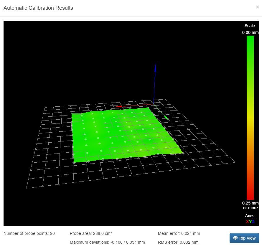
                                            This is the best bed mapping that I've ever had on the printer since running duet wifi.

                                            1 Reply Last reply Reply Quote 0
                                            • DjDemonD
                                              DjDemonD last edited by

                                              Excellent results that's very satisfying.

                                              Yeah they are quite tough the piezo's. On my test rig I've slammed it into the test bed so hard and so many times, it broke the bracket holding the module, but the piezo was still working like a champ. I've had a few de-soldered wires but soldered them back on with little or no drama. One of the issues moving this forward into a consumer unit is the fragility of the soldered connections on the piezo. My thinking is integrate the control board into the sensor module, thereby reducing the mobility in these wires to zero. It also reduces the (theoretical at this point) risk of interference on the lead to the piezo causing issues. There is another idea involving making the piezo part of the circuit and placing that in between the two parts of the assembly.

                                              Simon. Precision Piezo Z-Probe Technology
                                              www.precisionpiezo.co.uk
                                              PT1000 cartridge sensors NOW IN, just attach to your Duet board directly!

                                              1 Reply Last reply Reply Quote 0
                                              • kraegar
                                                kraegar last edited by

                                                Talked to a few people at MRRF and handed out some piezo's to a couple guys who had ideas about how to cut the holes more precisely, without any damage. Hopefully I'll have more info on their results soon.

                                                Co-Creator of the RailcoreII CoreXY printer
                                                https://www.thingiverse.com/thing:2407174

                                                1 Reply Last reply Reply Quote 0
                                                • DjDemonD
                                                  DjDemonD last edited by

                                                  That sounds great. Mike (Leadinglights) has developed a method of cutting them on a lathe. Reasonably neat cuts too. That being said none of the discs I have drilled have failed to perform initially or since.

                                                  I hope at some point we can source or have made piezo's with holes in at manufacture.

                                                  Simon. Precision Piezo Z-Probe Technology
                                                  www.precisionpiezo.co.uk
                                                  PT1000 cartridge sensors NOW IN, just attach to your Duet board directly!

                                                  1 Reply Last reply Reply Quote 0
                                                  • DjDemonD
                                                    DjDemonD last edited by

                                                    Okay so Idris and I are getting closer to having a drop in module ready. More or less settled on the design, just a bit of tweaking. It's done several thousand probes on the rig with no issues. Very stiff as it turns out you don't need any noticeable vertical compliance to get a trigger. Idris is making a custom pcb for it.

                                                    Should be a case of remove hot end, insert module between hot end and extruder/carriage and then plug in your endstop wire. It's for groove mount but could be easily adapted with a few bolt holes for screw mounting.

                                                    It's small around 30x20x18mm. Should illuminate on trigger (but will also make a solid colour version also).

                                                    Aiming for around £25 delivered (UK) for final version. The initial units will be considered beta units and be £19.99 delivered (UK) on the assumption we will get some feedback on improving the product.

                                                    International postage will be by individual postage quote.

                                                    Simon. Precision Piezo Z-Probe Technology
                                                    www.precisionpiezo.co.uk
                                                    PT1000 cartridge sensors NOW IN, just attach to your Duet board directly!

                                                    1 Reply Last reply Reply Quote 0
                                                    • kraegar
                                                      kraegar last edited by

                                                      So this would be a piezo with a hole for a bowden, and you just drop it over the top of your groovemount (around the bowden)?

                                                      Co-Creator of the RailcoreII CoreXY printer
                                                      https://www.thingiverse.com/thing:2407174

                                                      1 Reply Last reply Reply Quote 0
                                                      • First post
                                                        Last post
                                                      Unless otherwise noted, all forum content is licensed under CC-BY-SA