Configuring 12864 LCD on Maestro?
-
Does the Ender with the original electronics have anything connected to the EXP1 and EXP2 connectors? I am wondering whether those connectors might duplicate the pins on EXP3 but in a manner compatible with the RepRapDiscount display. You could use a multimeter to check whether the pins on EXP3 are also connected to EXP1 and EXP2, and if so what the pinout is.
-
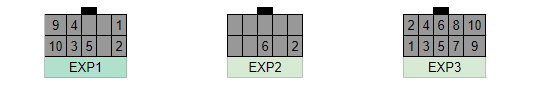
The Ender display has 3 connectors EXP 1 to EXP 3. Some of th pins of EXP 1 and EXP 3 are named.
EXP 1 from the pcb side:

EXP 3 from the pcb side:

Some pins are have the same signals. EXP 2 has no named pins.
Maybe it's possible to use 2 standard 10pin cable to connect EXP 1-3 from the Display to Maestro EXP 1 and EXP 2. But until now I didn't have the time to measure and check if it's possible. I'll try to do the next days.
-
I can check pinout. I know that exp2 does not work with duets exp2. It probably shorts as leds go out
-
Maybe 2 cables (10 pin). EXP 1 LCD to EXP 1 Maestro and EXP 3 LCD to EXP 2 Maestro.
EXP 1 LCD to EXP 1 Maestro is almost perfect. We only have to check wether Beep and ENC_SW is on EXP 1 LCD.
-
Here if if i did not missbeeped something
-
@arnd13 Hi thank you (i am an absolute beginner as well) this has solved my problem you have got my screen working now i just have to refine it
Thank's again -
@arnd13
Looks like vcc, gnd, buzz and enc_sw will work on exp1, you only need to cut slot in lcd connector and flip ribbon cable?! I will try that.
Another way is just to cut ribbon cable and crimp dupont pins, then use connectors found on pc for power,hdd, reset. They come in multiple sizes and could be salvaged -
@dc42 @arnd13 I can confirm that display works on EXP1. You need to cut a slot to opposite side of the LCD EXP1 and insert the ribbon cable "the wrong way". Further more if you cut slot on EXP2 on LCD and insert ribbon cable "the wrong way" and connect it to DUET Maestro EXP2, you will have fully functional LCD.
Only encoder will be reversed.
Wow, the trouble i went through crimping those cables when i only needed to cut out 2 slots...P.S. Probably i was too quick with the post. Weird, but when duet is powered through USB, everything works but when through power terminals the display is blank.
Never mind, had it disabled in config.
So you dont have to enable it in config if its powered by USB but you do when it is power through power terminals -
I tried using menu from @Greg3D , i think and it would not go into menu items so i edited main file and now its working. Attached menu
0_1543946960070_Maestro_Menu.gcode
Did not let to attach .zip, rename .gcode extension to .zip -
I also used those menu files and had to edit them. Menus are only for the base functions but a good base to extend with additional functions.
A mix between those files and the CraneQuadMenuFiles would be the best solution.
-
Whew, ok.. pretty confusing thread. I'm ready right now to connect the Maestro to my stock Ender 3 Pro display. Do we have consensus on what needs to be done? If the the display is standard off the shelf used by Creality why is flipping the cable necessary? Do we actually need two cables? Is the encoder finally reversed when all is wired, or is there a way to correct that? The info I found is pretty limited on schematics. What connectors should be used on the Maestro end, and the display end?
Scratch built CoreXY with Maestro
Heavily modified Ender 3 with Maestro
MPCNC work in progress with Duet WiFi -
The most common connection scheme for 12864 displays is the one used by the RepRapDiscount Smart Graphics Controller. This is an open source design described at https://reprap.org/wiki/RepRapDiscount_Full_Graphic_Smart_Controller. That was in turn based on the connections used by 20x4 text displays. Unfortunately the display on the Ender 3 uses a different scheme.
A single 10-way connection would in principle be sufficient for a display without a SD card socket, but doesn't provide enough pins for both the LCD and the SD card.
Duet WiFi hardware designer and firmware engineer
Please do not ask me for Duet support via PM or email, use the forum
http://www.escher3d.com, https://miscsolutions.wordpress.com -
@dc42 said in Configuring 12864 LCD on Maestro?:
The most common connection scheme for 12864 displays is the one used by the RepRapDiscount Smart Graphics Controller. This is an open source design described at https://reprap.org/wiki/RepRapDiscount_Full_Graphic_Smart_Controller. That was in turn based on the connections used by 20x4 text displays. Unfortunately the display on the Ender 3 uses a different scheme.
A single 10-way connection would in principle be sufficient for a display without a SD card socket, but doesn't provide enough pins for both the LCD and the SD card.
Figures
 And apparently Creality inverted the pins. The display has no SD card. They managed to get the display and the encoder over a single 8 pin cable to their CPU board. I guess the Maestro has pins needed for the encoder on one connector and the display on another one.
 -
@3dmntbighker, Yes, there is consensus. There are 2 ways you can connect your display.
- You use your cable, cut one end on it, get some dupont connectors and wire it according to this diagram:

If encoder is reversed, you flip 2 bottom wires(as per pic) on Duets EXP2(left connector on pic) - method is to use 2 10pin cables(so you need to buy another one)
a. on duet, connect it normal way
b. on ender 3 display, connect it flipped where locator clips face beeper.
Duet exp1 to LCD exp1 flipped
Duet exp2 to LCD exp2 flipped
Dont forget to add M918 P1 E4 to your config.g
- You use your cable, cut one end on it, get some dupont connectors and wire it according to this diagram:
-
Some more of the insights. Using two cable method lcd shows some artifacts. When connected to exp3 and using diy'ed single cable artifacts are absent


-
If encoder is reversed, you flip 2 bottom wires(as per pic) on Duets EXP2(left connector on pic)
You can also reverse the encoder direction in the M918 command that configures the display and encoder.
-
Thanks for all the help. My cables will arrive tomorrow.
Has anyone determined if the Ender display can support the second SD card? And what may be lacking to add it? Just curious if a full size SD card is possible to add.
-
My cables arrived, and I have the display working. It seems the default menu system with RC5 doesn't work out of the box. I messed around a bit before leaving for work, but has anyone put together a working menu system (starting point) for the Ender 3. It appears that a single file makes the whole RC5 menu system operate named "menu" that is absent on my Maestro. (edit: OK, I noticed this is mentioned in the RC5 release notes, so I guess DC is workin on it already)
I also notice the artifacts mentioned with the two cable solution. I hope we can track down the cause at some point.
Thanks to everyone who has pitched in.
-
Adding SD card to the LCD is no go. You can add it as a separate module you can get on ebay for few quid:
Just for illustration:
https://www.ebay.com/itm/3D-printer-SD-external-card-reader-MKS-Slot-V1-1-and-MKS-Slot2-2-8-inch-U-disk/222920755412?hash=item33e71cc8d4 matuTHLib1EHTKR3OVhUcHw:rk:1:pf:0
I have attached somewhat fixed basic menu few posts above
-
@agniusm said in Configuring 12864 LCD on Maestro?:
@arnd13
Looks like vcc, gnd, buzz and enc_sw will work on exp1, you only need to cut slot in lcd connector and flip ribbon cable?! I will try that.
Another way is just to cut ribbon cable and crimp dupont pins, then use connectors found on pc for power,hdd, reset. They come in multiple sizes and could be salvagedI just filed off the bit on the cable connector that indexes the cable. Less than a minute and I didn't butcher the board
")