@jay_s_uk OKay, that`s sad. But thanks for your quick supply!
Best posts made by trulm
-
RE: Beginner mode for DWC?posted in Duet Web Control
-
RE: Input shaping, Recording of data doesn't want to be completeposted in Tuning and tweaking
@jay_s_uk Thank you for the really helpful information. You were absolutely right, this was the solution.
Latest posts made by trulm
-
RE: Beginner mode for DWC?posted in Duet Web Control
@jay_s_uk OKay, that`s sad. But thanks for your quick supply!
-
Beginner mode for DWC?posted in Duet Web Control
Hi all,
I'm looking for a way to use Duet Web Control (DWC) in a secure mode or block certain functions. Does anyone have experience with this or know of a solution?
Specifically, I've got a printer that I've converted to Duet3d and I'd like to make it available to my students, who are beginners in 3D printing. But I'm worried that DWC is too extensive and could lead to accidental changes to the config, for example. Is there a way to lock some areas or functions in dwc with a passkey or something?
I look forward to your answers and suggestions!
-
RE: Input shaping, Recording of data doesn't want to be completeposted in Tuning and tweaking
@jay_s_uk Thank you for the really helpful information. You were absolutely right, this was the solution.
-
RE: Input shaping, Recording of data doesn't want to be completeposted in Tuning and tweaking
@jay_s_uk
Duet3 mini5+ Firmware: 3.5.1
DWC Firmware: 3.4.0
Input Shaping Firmware: 3.4.7Unfortunately, I have nested my config using M98 commands and therefore cannot upload everything clearly here. If you let me know what might be relevant, I will of course upload the relevant section.
; config.g
; Configuration file for RepRapFirmware on Duet 3 Mini 5+ WiFi
; executed by the firmware on start-up

; Printer: M350pro
; Stand 2025-02-13


if {network.interfaces[0].type = "ethernet"}
    M552 P192.168.1.14 S1
else
    M552 S1

; General
G90 																		; absolute coordinates
M83 																		; relative extruder moves
M550 P"M350pro" 															; set hostname

; Accessories
;M918 P0 E1 F2000000 														; configure direct-connect display
;M98 P"start_wifi.g"														; start and connect Wifi
;M98 P"machine_PanelDue.g"													; configure PanelDue
M98 P"machine_accelerometer.g"												; configure accelerometer for input shaping

; Smart Drivers
M98 P"machine_drivers.g"													; configure Drivers

; Motor Idle Current Reduction
M906 I30 																	; set motor current idle factor
M84 S30 																	; set motor current idle timeout

; Axes
M98 P"machine_axisdimension.g"												; configure Axes

; Extruders
M98 P"machine_extruder.g"													; configure the Extruder

; Kinematics
M669 K0 																	; configure Cartesian kinematics

; Probes
M98 P"machine_zprobe.g"														; configure the z probes

; Endstops
M98 P"machine_endstops.g"													; configure Endstops

; Sensors
M98 P"machine_sensors.g"													; configure all sensors

; mesh bed compensation
M557 X-105:145 Y-70:110 P12:12												; define grid for mesh bed compensation with 12x12Points

; Heaters
M98 P"machine_heaters.g"													; configure all heaters

; Heated bed
M140 P0 H0 																	; configure heated bed #0

; Fans
M98 P"machine_fans.g"														; configure all Fans

; Tools
M98 P"machine_tools.g"														; configure all tools

; electronics temperature monitor adjustment
M912 P0 S-7	 																; Set electronics temperature monitor adjustment for mcu```
; machine_accelerometer.g ; 2025-02-06 M955 P0 C"spi.cs2+spi.cs1" I61 ; all wires connected to temp DB connector, no temperature daughterboard -
Input shaping, Recording of data doesn't want to be completeposted in Tuning and tweaking
Hi, I'm new to the world of Input Shaping and I have a small but annoying problem. Every time I start recording an Input Shaping profile, the DWC popup never finishes. I took this picture 5 minutes after starting the recording. Do you have any idea where I can find my problem?
My Settings:
DiY Printer
E3D Revo Hotend
Duet3 mini5+
Duet3d Accelerometer for Revo Hotend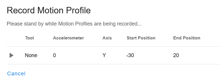
-
RE: Scanning Z Probe giving erratic Z valuesposted in Duet Hardware and wiring
Hi, I had the very similar problems with the SZP, but I fixed it with your instructions in this thread.
Now I can use the SZP to do a 3-point bed leveling, but when I start the G29 or G32, all points of the mesh are on 0.0mm deviation.
Do you have any tips on what the problem might be, or have you ever had a similar case?
I use the 12mm coil.
; machine_zprobe.g

; 2024-08-21

; Z-Scanning Probe for T0
M558 K1 P11 C"120.i2c.ldc1612" H5 F6000 T6000			; configure scanning probe t0 via slot #1
M308 A"SZP coil" S10 Y"thermistor" P"120.temp2"			; thermistor on SZP coil
G31 P9400 X32 Y0 Z1.7 K1					; set t0 Z probe trigger value, offset and trigger height, Z4 means 4mm offset Probe to Nozzle
M558.2 K1 S15 R139620						; set drive current and reading offset

; Z-Scanning Probe for T1
;M558 K2 P11 C"121.i2c.ldc1612" H5 F6000 T6000			; configure scanning probe t1 via slot #2
;G31 P500 X0 Y0 Z0.7 						; set Z probe trigger value, offset and trigger height

; Mesh Bed Compensation
M557 X-180:180 Y-180:180 S18					; define grid for mesh bed compensation
; bed.g ; 2024-08-21 ; Heat bed and nozzle ;M140 S60 ; set the bed to 60C M104 T0 S220 ; set the t0 to 220C ; prepare printer G1 Z2 F800 ;M190 S60 ; wait for the bed to reach 60C M109 T0 S220 ; wait for the nozzle to read 220C M98 P"Bedleveling.g" ; start 3-point-Leveling ; Clear any bed transform G29 S2 ; Does the same as M561! ; mesh bed compensation M557 X-175:175 Y-175:175 S20:20 ; define grid for mesh bed compensation G29 K1 S0 ; Probe the bed, save height map to "heightmap.csv" and enable mesh bed compensation; Bedleveling.g ; Bedleveling with 3 Points ; 2024-08-20 ; Z-leveling with 3 points and scanning probe after Z-homing G28 ; home all axes while true G30 P0 X-180 Y-180 Z-99999 K1 ; probe point 0 near Z1-joint G30 P1 X0 Y180 Z-99999 K1 ; probe point 1 near Z2-joint G30 P2 X180 Y-180 Z-99999 S3 K1 ; probe point 2 near Z3-joint and calibrate all Z-motors if abs(move.calibration.initial.deviation) < 0.01 || iterations >3 break ; move to startposition G1 Y0 Z50 F1000 G28 XU; _3_Mesh_Bed.g ; 2024-08-12 M291 P"Do you want to Mesh Your Bed?" S3 M291 R"PREPARING BED COMPENSATION (MESHING)" P"Now homing and heating up (nozzle & bed). Wait for further instructions." S0 ; preparing G28 ;M140 S60 ; Start heating bed to 60c ;M190 S60 ; wait for Bed temperature G10 P0 S200 ; turn on t0 ;Beep 3 times M300 S600 P250 G4 P401 M300 S600 P250 G4 P401 M300 S600 P250 G4 P401 M291 R"NOTICE" P"Bed Mesh Starting." S2 G32 ; Executes the bed mesh procedure defined in bed.g ; place t0 and bed G1 Z20 F800 ; raise bed G1 X0 Y0 F4000 ; center t0 ;Beep 3 times M300 S1500 P200 G4 P250 M300 S1000 P200 G4 P250 M300 S500 P200 G4 P250 G1 Z100 F800 ; Move the bed to Z 100mm from the nozzle so that there is room to retract the z probe if desired. G1 X0 Y0 F4000 ; Move the bed to Z 100mm from the nozzle so that there is room to retract the z probe if desired. M291 R"NOTICE" P"Do you want to turn off your heaters (Bed & Nozzle)?" S3 M140 S0 ; turn off heated bed G10 P0 S0 ; turn off t0 -
RE: Roto Toolboard and Scanning Probe issuesposted in Duet Hardware and wiring
@dc42 @gloomyandy Thanks to both of you for your help!
It's nice to see that the community here helps each other. This is no longer the case in many other forums
-
RE: Roto Toolboard and Scanning Probe issuesposted in Duet Hardware and wiring
Thanks for your answer.
What exactly does the trigger value (Pnnn) in the G91 command mean? Could that be the reason? (line60 in the config)Here are my complete config:
; Configuration file for RepRapFirmware on Duet 3 Mini 5+ WiFi
; executed by the firmware on start-up

; Stand 2024-08-07

; General
G90																		; absolute coordinates
M83 																	; relative extruder moves
M550 P"Idechs" 															; set hostname
M911 S19.8 R22 P"M913 X0 Y0 G91 M83 G1 Z3 E-5 F1000" 					; set voltage thresholds and actions to run on power loss

; Accessories
M575 P1 S0 B57600 														; configure PanelDue support

G4 S2																	; Wait 2sec for the CAN expansion boards to become available

; Accelerometers
;M955 P120.0 I50 														; configure accelerometer on board #120
;M955 P121.0 I50 														; configure accelerometer on board #121

; Smart Drivers
M569 P0.0 S0 D2															; driver 0.1 goes forwards (Z1 axis)
M569 P0.1 S1 D2															; driver 0.1 goes backwards (Z2 axis)
M569 P0.2 S1 D2															; driver 0.2 goes backwards (Z3 axis)
M569 P0.3 S0 D2															; driver 0.3 goes backwards (X axis)
M569 P0.4 S1 D2															; driver 0.4 goes forwards (Y axis)
M569 P0.5 S0 D2															; driver 0.5 goes forwards (U axis)
M569 P120.0 S1 D2														; driver 120.0 goes forwards (extruder t0)
M569 P121.0 S1 D2														; driver 121.0 goes forwards (extruder t1)

; Axes
M584 X0.3 Y0.4 U0.5 Z0.0:0.1:0.2										; create axes
M350 X16 Y16 Z16 U16 I1													; configure microstepping with interpolation
M906 X1680 Y1680 Z1600 U1680											; set axis driver currents
M92 X160 Y160 Z320 U160													; configure steps per mm
M208 X-306:200 Y-200:206 Z0:460 U-200:281								; set minimum and maximum axis limits
M566 X900 Y900 Z12 U900													; set maximum instantaneous speed changes (mm/min)
M203 X6000 Y6000 Z1000 U6000											; set maximum speeds (mm/min)
M201 X500 Y500 Z10 U500													; set accelerations (mm/s^2)

; Motor Idle Current Reduction
M906 I30																; set motor current idle factor
M84 S30																	; set motor current idle timeout

; Extruders
M584 E120.0:121.0														; set extruder mapping
M350 E16:16 I1															; configure microstepping with interpolation
M906 E450:450															; set extruder driver currents
M92 E2682:2682															; configure steps per mm
M566 E120:120															; set maximum instantaneous speed changes (mm/min)
M203 E3600:3600															; set maximum speeds (mm/min)
M201 E3000:3000															; set accelerations (mm/s^2)

; Kinematics
M669 K1 X1:1:0:0 Y1:-1:0:-1 Z0:0:1:0 U0:0:0:1							; configure CoreXY with Markforged kinematics U-Axis
M671 X-204.5:0:204.5 Y-204.5:204.5:-204.5 S1.0							; Z pivot points Z-axes

; Probes
M558 K1 P11 C"120.i2c.ldc1612" H5 F6000 T6000							; configure scanning probe t0 via slot #1
G31 P500 X32 Y0 Z4														; set t0 Z probe trigger value, offset and trigger height
;M558 K2 P11 C"121.i2c.ldc1612" H5 F6000 T6000							; configure scanning probe t1 via slot #2
;G31 P500 X0 Y0 Z0.7 													; set Z probe trigger value, offset and trigger height

; Endstops
M574 X1 S1 P"120.io0.in"												; configure X axis endstop
M574 Y2 S1 P"io4.in"													; configure Y axis endstop
M574 Z2 S1 P"io1.in+io2.in+io3.in"										; configure Z axis endstops
M574 U2 S1 P"121.io0.in"												; configure U axis endstop

; Mesh Bed Compensation
M557 X-175:175 Y-175:175 S20:20											; define grid for mesh bed compensation

; Sensors
M308 S0 P"temp0" Y"thermistor" A"Heated Bed" T100000 B4725 C7.06e-8 					; configure sensor #0
M308 S1 P"120.temp0" Y"thermistor" A"Nozzle T0" T100000 B4658 C6.5338987554e-08			; configure sensor #1
M308 S2 P"121.temp0" Y"thermistor" A"Nozzle T1" T100000 B4658 C6.5338987554e-08			; configure sensor #2
M308 S3 P"120.temp1" Y"thermistor" A"Heatsink T0" T100000 B4725 C7.06e-8				; configure sensor #3
M308 S4 P"121.temp1" Y"thermistor" A"Heatsink T1" T100000 B4725 C7.06e-8 				; configure sensor #4

; Heaters
M950 H0 C"out0" T0 														; create heater #0 heated bed
M143 H0 P0 T0 C0 S120 A0 												; configure heater monitor #0 for heater #0
M307 H0 R2.43 D5.5 E1.35 K0.56 B0 										; configure model of heater #0
M950 H1 C"120.out0" T1 													; create heater #1 T0
M143 H1 P0 T1 C0 S300 A0 												; configure heater monitor #0 for heater #1 T0
M307 H1 R2.43 D5.5 E1.35 K0.56 B0 										; configure model of heater #1 T0
M950 H2 C"121.out0" T2	 												; create heater #2 T1
M143 H2 P0 T1 C0 S300 A0 												; configure heater monitor #0 for heater #2
M307 H2 R2.43 D5.5 E1.35 K0.56 B0 										; configure model of heater #2

; Heated beds
M140 P0 H0 R60															; configure heated bed #0

; Fans
M950 F0 C"out3" 														; create fan #0 Electricl Fan
M106 P0 C"Electrical Fan" S0 B0.1 H0 T40:90 							; configure fan #0
M950 F1 C"120.out2+out2.tach" 											; create fan #1 Heatsink t0
M106 P1 C"Heatsink Fan T0" S0 B0.1 H3 T30:50							; configure fan #1 bezogen auf 120.temp1
M950 F2 C"121.out2+out2.tach" 											; create fan #2  Heatsink t1
M106 P2 C"Heatsink Fan T1" S0 B0.1 H4 T30:50 							; configure fan #2
M950 F3 C"120.out1" 													; create fan #3 Partcooling t0
M106 P3 C"Partcooling Fan T0" S0 L0 X255 B0.1 							; configure fan #3
M950 F4 C"121.out1" 													; create fan #4 Partcooling t1
M106 P4 C"Partcooling Fan T1" S0 L0 X255 B0.1 							; configure fan #4

; Tools
M563 P0 D0 H1 F3 														; create tool #0
M568 P0 R160 S220														; set initial tool #0 active and standby temperatures to 20C
M563 P1 D1 H2 F4 														; create tool #1
M568 P1 R0 S0 															; set initial tool #1 active and standby temperatures to 20C
And here are the M122 results:
	m122
=== Diagnostics ===
RepRapFirmware for Duet 3 Mini 5+ version 3.5.2 (2024-06-11 17:14:16) running on Duet 3 Mini5plus WiFi (standalone mode)
Board ID: 3U6ZP-DN6KL-K65J0-409NA-NF02Z-ZVQH8
Used output buffers: 1 of 40 (37 max)
Error in macro line 65 while starting up: invalid Z probe index
=== RTOS ===
Static ram: 103368
Dynamic ram: 123760 of which 12 recycled
Never used RAM 11348, free system stack 138 words
Tasks: NETWORK(1,ready,19.4%,217) LASER(5,nWait 7,0.0%,269) HEAT(3,nWait 6,0.0%,335) Move(4,nWait 6,0.0%,285) CanReceiv(6,nWait 1,0.1%,796) CanSender(5,nWait 7,0.0%,336) CanClock(7,delaying,0.0%,348) TMC(4,delaying,1.6%,67) MAIN(1,running,77.8%,455) IDLE(0,ready,0.1%,29) AIN(4,delaying,0.9%,259), total 100.0%
Owned mutexes: WiFi(NETWORK)
=== Platform ===
Last reset 00:03:02 ago, cause: power up
Last software reset time unknown, reason: HeatTaskStuck, Gcodes spinning, available RAM 53972, slot 2
Software reset code 0x0143 HFSR 0x00000000 CFSR 0x00000000 ICSR 0x0000080f BFAR 0xe000ed38 SP 0x20013938 Task IDLE Freestk 17002 ok
Stack: 00000000 2001329c 10000000 e000e000 20000f4c 000a1821 000a2004 61000000 000a1fed 00000000 20013298 2002cd20 20013290 00000000 00004e22 2001882c 0009e359 20025198 20025110 000546f9 00057647 20025198 2002519c 2002511c 20025118 a5a5a500 41c9b550
Error status: 0x00
Aux0 errors 0,1,0
MCU revision 3, ADC conversions started 183006, completed 183005, timed out 0, errs 0
MCU temperature: min 23.9, current 40.5, max 40.7
Supply voltage: min 23.6, current 24.1, max 24.2, under voltage events: 0, over voltage events: 0, power good: yes
Heap OK, handles allocated/used 99/2, heap memory allocated/used/recyclable 2048/104/72, gc cycles 0
Events: 0 queued, 0 completed
Driver 0: standstill, SG min 0, read errors 0, write errors 0, ifcnt 15, reads 16516, writes 15, timeouts 0, DMA errors 0, CC errors 0
Driver 1: standstill, SG min 0, read errors 0, write errors 0, ifcnt 15, reads 16516, writes 15, timeouts 0, DMA errors 0, CC errors 0
Driver 2: standstill, SG min 0, read errors 0, write errors 0, ifcnt 15, reads 16516, writes 15, timeouts 0, DMA errors 0, CC errors 0
Driver 3: standstill, SG min 0, read errors 0, write errors 0, ifcnt 15, reads 16516, writes 15, timeouts 0, DMA errors 0, CC errors 0
Driver 4: standstill, SG min 0, read errors 0, write errors 0, ifcnt 15, reads 16516, writes 15, timeouts 0, DMA errors 0, CC errors 0
Driver 5: standstill, SG min 0, read errors 0, write errors 0, ifcnt 15, reads 16516, writes 15, timeouts 0, DMA errors 0, CC errors 0
Driver 6: standstill, SG min 0, read errors 0, write errors 0, ifcnt 10, reads 16521, writes 10, timeouts 0, DMA errors 0, CC errors 0
Date/time: 2024-08-07 08:22:43
Cache data hit count 342072592
Slowest loop: 99.65ms; fastest: 0.16ms
=== Storage ===
Free file entries: 20
SD card 0 detected, interface speed: 22.5MBytes/sec
SD card longest read time 4.0ms, write time 0.0ms, max retries 0
=== Move ===
DMs created 83, segments created 3, maxWait 63468ms, bed compensation in use: none, height map offset 0.000, max steps late 0, min interval 0, bad calcs 0, ebfmin 0.00, ebfmax 0.00
no step interrupt scheduled
Moves shaped first try 0, on retry 0, too short 0, wrong shape 0, maybepossible 0
=== DDARing 0 ===
Scheduled moves 17, completed 17, hiccups 0, stepErrors 0, LaErrors 0, Underruns [0, 0, 0], CDDA state -1
=== DDARing 1 ===
Scheduled moves 0, completed 0, hiccups 0, stepErrors 0, LaErrors 0, Underruns [0, 0, 0], CDDA state -1
=== Heat ===
Bed heaters 0 -1 -1 -1, chamber heaters -1 -1 -1 -1, ordering errs 0
=== GCodes ===
Movement locks held by null, null
HTTP is idle in state(s) 0
Telnet is idle in state(s) 0
File is idle in state(s) 0
USB is idle in state(s) 0
Aux is idle in state(s) 0
Trigger is idle in state(s) 0
Queue is idle in state(s) 0
LCD is idle in state(s) 0
SBC is idle in state(s) 0
Daemon is idle in state(s) 0
Aux2 is idle in state(s) 0
Autopause is idle in state(s) 0
File2 is idle in state(s) 0
Queue2 is idle in state(s) 0
Q0 segments left 0, axes/extruders owned 0x0000007
Code queue 0 is empty
Q1 segments left 0, axes/extruders owned 0x0000000
Code queue 1 is empty
=== CAN ===
Messages queued 1677, received 7287, lost 0, errs 0, boc 0
Longest wait 1ms for reply type 6034, peak Tx sync delay 13, free buffers 26 (min 25), ts 911/910/0
Tx timeouts 0,0,0,0,0,0
=== Network ===
Slowest loop: 15.32ms; fastest: 0.00ms
Responder states: MQTT(0) HTTP(0) HTTP(0) HTTP(0) HTTP(0) FTP(0) Telnet(0)
HTTP sessions: 1 of 8
=== WiFi ===
Interface state: active
Module is connected to access point
Failed messages: pending 0, notrdy 0, noresp 0
Firmware version 1.26
MAC address e8:68:e7:e1:4d:e5
Module reset reason: Power up, Vcc 3.38, flash size 2097152, free heap 24792
WiFi IP address 192.168.3.108
Signal strength -72dBm, channel 0, mode 802.11n, reconnections 0
Clock register 00002002
Socket states: 0 0 0 0 0 0 0 0
...and the M98
M98 P"config.g"
Error: invalid Z probe index
Warning: Heater 0 predicted maximum temperature at full power is 321°C
... and the Z-leveling macro
; Z-leveling with 3 points and scanning probe after Z-homing G28 ; home all axes G30 P0 X-180 Y-180 Z-99999 K1 ; probe point 0 near Z1-joint G30 P1 X0 Y180 Z-99999 K1 ; probe point 1 near Z2-joint G30 P2 X180 Y-180 Z-99999 S3 K1 ; probe point 2 near Z3-joint and calibrate all Z-motors -
Roto Toolboard and Scanning Probe issuesposted in Duet Hardware and wiring
Hi guys,
I have built an Idex printer with Mini5+, e3d Roto and Roto toolboards. Now I want to implement the first scanning probe but I always get the message "Invalid Z probe index".
When I start a bed leveling the printer says "G30: Probe already triggered at start of probing move".
Do you have any idea where I can find the problem?This ist part of the config file.
; Probes
M558 K1 P11 C"120.i2c.ldc1612" H5 F6000 T6000					; configure scanning probe t0 via slot #1
G31 P500 X32 Y0 Z4								; set t0 Z probe trigger value, offset and trigger height
This is my macro to start the leveling.
; Z-leveling with 3 points and scanning probe after Z-homing
G28											; home all axes
G30 P0 X-180 Y-180 Z-99999 K1								; probe point 0 near Z1-joint
G30 P1 X0 Y180 Z-99999 K1								; probe point 1 near Z2-joint
G30 P2 X180 Y-180 Z-99999 S3 K1								; probe point 2 near Z3-joint and calibrate all Z-motors
All Boards are updated to the latest release.
The scanning probe is mounted with a bracket similiar to the duet3d example on github. -
3 independent Z motors - how can the bed "dance"?posted in MultiAxis Printing
Hi guys,
I have built a printer with three independent Z motors. I created the Z axis with M584 and it works fine, including the homing.
But is there a way to move the motors individually? The reason is that I want to build a macro to show the independent Z-drive. I want the bed to "dance".