I have tested the new version and I have to say it really is a huge improvement. For me, it's the best and most important update so far. My printer is heavy and has quite a high mass that is being moved. Now I can increase the acceleration and jerk with higher print speeds and a much better surface as a result. The printer used to make a lot of noise, especially when changing direction quickly (contours of figures etc.), which is no longer the case. In short, my printer now finally prints the way I always imagined it would, in terms of speed, noise and quality. Thank you for the release and the work involved.
Best posts made by N3XT3D
-
RE: RepRapFirmware 3.6.0-alpha.2 for Duet main boards availableposted in Beta Firmware
Latest posts made by N3XT3D
-
RE: RepRapFirmware 3.6.0-alpha.2 for Duet main boards availableposted in Beta Firmware
I have tested the new version and I have to say it really is a huge improvement. For me, it's the best and most important update so far. My printer is heavy and has quite a high mass that is being moved. Now I can increase the acceleration and jerk with higher print speeds and a much better surface as a result. The printer used to make a lot of noise, especially when changing direction quickly (contours of figures etc.), which is no longer the case. In short, my printer now finally prints the way I always imagined it would, in terms of speed, noise and quality. Thank you for the release and the work involved.
-
RE: Bed Origin and axis Limitposted in Using Duet Controllers
@engikeneer this is really a clever solution. Exately what I was looking for! Thanks
")
-
RE: Bed Origin and axis Limitposted in Using Duet Controllers
@mrehorstdmd Yes 1-2 mm are definitely not a problem. For me, it's all about being able to reach a brush that is outside of the printable area, for example. That's all
")
I think I'll then shorten the flag as much as necessary so as not to complicate things.
Thank you for the hard work and the detailed answers.
Have a nice weekend.
-
RE: Bed Origin and axis Limitposted in Using Duet Controllers
First of all, thank you for all the help.
ok maybe there were too many different views. Sorry
At first I thought I would leave the flag longer and I can shorten it later, but then I thought why not leave it longer and relate the minimun of the axis to the trigger point. Too short wouldn't be good either.
My idea is to leave the flag a little longer (not necessarily as much as in the illustration. Let's say 5mm) and to use the "softlimit" to limit the axis so that it does not reach the mechanical end stop.
Maybe I'm just confused, but is it possible to say that the limit of an axis is 5mm behind the trigger?
-
RE: Bed Origin and axis Limitposted in Using Duet Controllers
@mrehorstdmd But even with this variant there is the problem that you can never drive past the trigger point of the end stop. Or am I wrong?
For example, these two views would be the point at which the optical end stop triggers. You couldn't go any further into the negative and I wouldn't be able to use 20mm of the rail


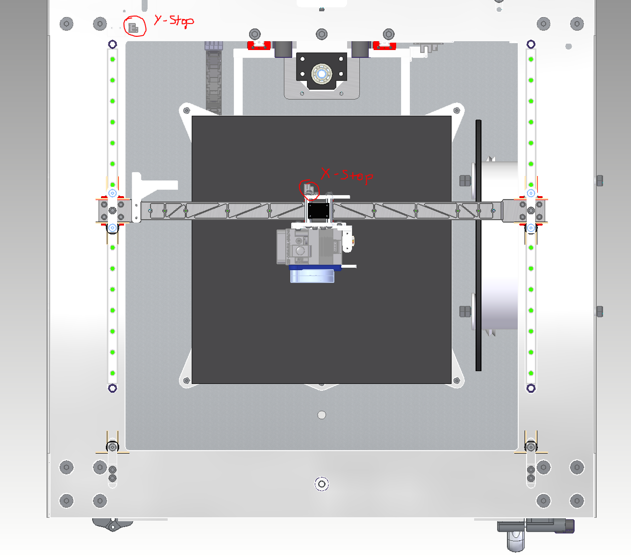
As an example for the X axis, the limit of the axis and the origin of the bed would have to be set separately (in relation to the trigger point of the respective axis).
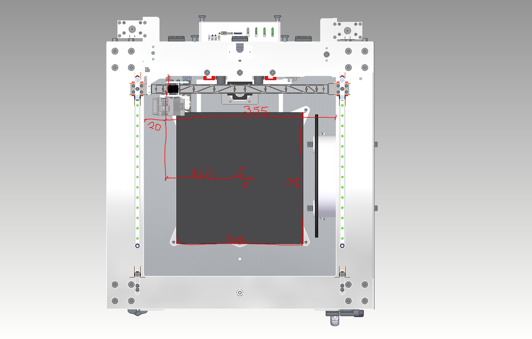
Otherwise it would not be possible to use the entire length of the rail, as shown in the next picture
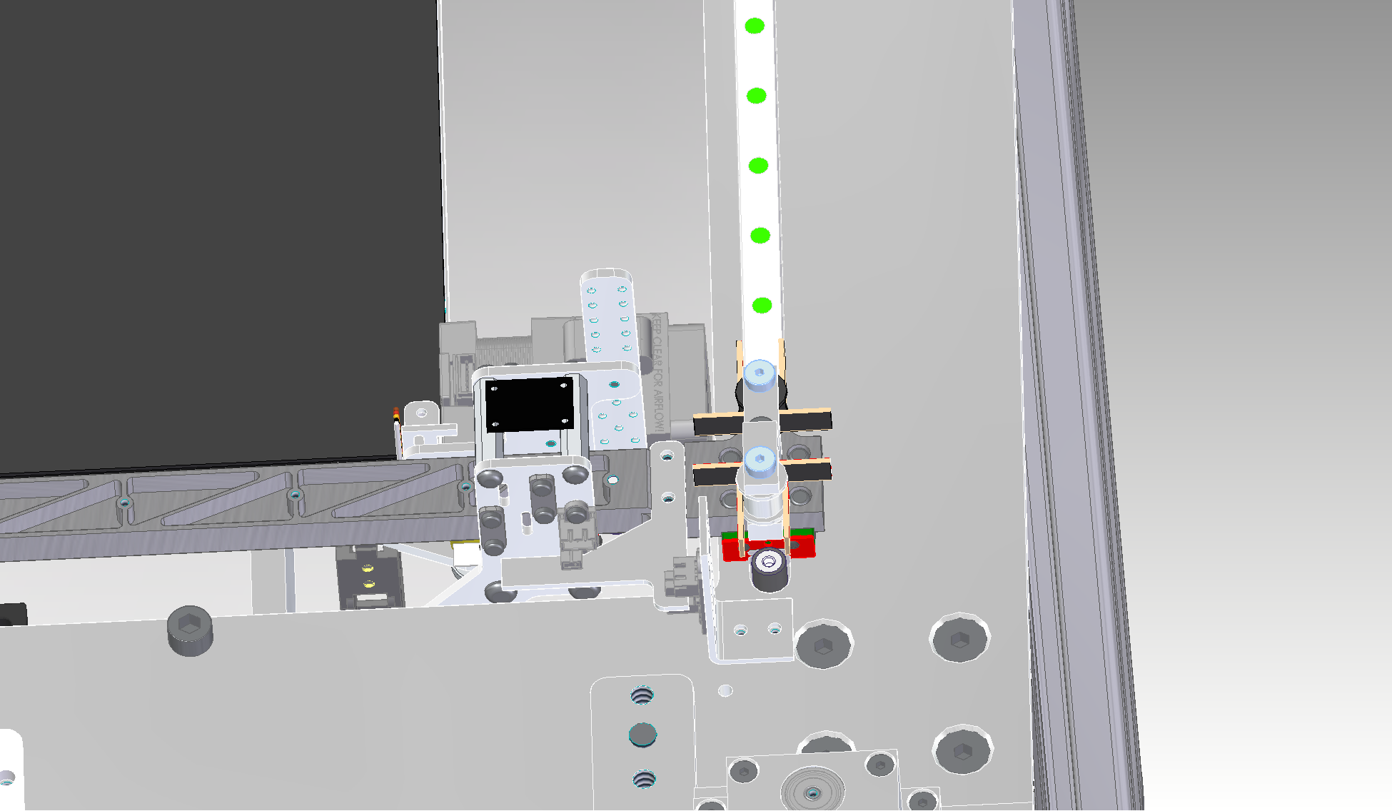
I hope the screenshots from the different perspectives and what I want to explain are understandable.
-
RE: Bed Origin and axis Limitposted in Using Duet Controllers
@mrehorstdmd Thanks for the tips.
Putting the origin point in the center of the bed should solve the problem.
I will leave the endstop layout as it is for the time being, as I already have some lasered aluminum parts here. But basically a good idea.
By the way, I have read some of the articles on the layout of Corexy printers and I would like to thank you for them.
This is the most helpful information you can get.So thank you
-
Bed Origin and axis Limitposted in Using Duet Controllers
Hello everybody.
For my new 3d printer project (Duet 2 Wifi), I installed optical end stops, which allow me to move the min and max of the axes beyond the trigger point.
This enables me to move each axis safely within its limits. However, this also has a direct effect on the bed origin point.Is it possible to set this independently, for example to reach a brush outside the print bed?
Thanks in advance
-
RE: Help needed with Duet 3 6hc TMC5160 StealthChop configposted in Tuning and tweaking
I have read through the documentation and will test and report it.
-
RE: Help needed with Duet 3 6hc TMC5160 StealthChop configposted in Tuning and tweaking
The volume is actually extremely loud throughout.
The faster the speed, the more extreme it becomes. If you print a cylinder with only one perimeter as a spiral, you will see very strong resonances in the print image due to the constant change in the speed of the motors due to the Corexy structure.
At some speeds the resonances are stronger, e.g. at 30mm/s at 60mm/s, on the other hand, the printer is "quietest", which is also outside the normal range. I have adjusted the M569 F parameter and tested between 1-10 during operation and at a standstill. The result would definitely be small.
I don't know how else to configure Coolstep, but I would definitely try it out. -
RE: Help needed with Duet 3 6hc TMC5160 StealthChop configposted in Tuning and tweaking
Exactly, I cross-checked via the console and the M350 command whether the parameters are active.