Duet3D Logo Duet3D
    • Tags
    • Documentation
    • Order
    • Register
    • Login
    1. Home
    2. Chuckonelli
    • Profile
    • Following 0
    • Followers 0
    • Topics 5
    • Posts 11
    • Best 1
    • Controversial 0
    • Groups 0

    Chuckonelli

    @Chuckonelli

    1
    Reputation
    4
    Profile views
    11
    Posts
    0
    Followers
    0
    Following
    Joined Last Online
    Location Schweiz Age 30

    Chuckonelli Unfollow Follow

    Best posts made by Chuckonelli

    • RE: Homing - Setback after endstop not working (homex.g, homey.g)

      @fcwilt
      Hello Frederick

      Yes it worked. Thank you.

      Maybe it didn't work because it's still at the endstop-triggering position and prevents any movement. I just misread ''terminate'' -> it seems it means both directions

      "H1 terminate the move when the endstop switch is triggered and set the axis position to the axis limit defined by M208. On delta printers, H1 also selects individual motor mode as for H2. Normally used with relative motor coordinates (see G91)."

      posted in Tuning and tweaking
      Chuckonelliundefined
      Chuckonelli

    Latest posts made by Chuckonelli

    • RE: Homing - Setback after endstop not working (homex.g, homey.g)

      @fcwilt
      Hello Frederick

      Yes it worked. Thank you.

      Maybe it didn't work because it's still at the endstop-triggering position and prevents any movement. I just misread ''terminate'' -> it seems it means both directions

      "H1 terminate the move when the endstop switch is triggered and set the axis position to the axis limit defined by M208. On delta printers, H1 also selects individual motor mode as for H2. Normally used with relative motor coordinates (see G91)."

      posted in Tuning and tweaking
      Chuckonelliundefined
      Chuckonelli
    • Homing - Setback after endstop not working (homex.g, homey.g)

      Hello all

      I have a quick question about the step-/setback after hitting/reaching the endstops in X- and Y-direction.

      It seems that my defined setback after hitting a Endstop is not working. First I'm homing the Y-Axis and after the X-Axis. In both .g-files I have implemented a relative move (away from the endstop) but the movement isn't executed. The printer homes the X-Axis without moving away from the Y-Endstop.

      The Endstop-Positions:
      ; Axis
      M208 X-180.2:180.2 Y-148.35:140.05 Z0:280 C0:240 S0

      Y-Axis: +140.05
      X-Axis: +180.2

      My homex.g:
      G91 ; use relative positioning
      G1 H2 X0.5 Y-0.5 F10000
      M400
      M913 X31 Y31
      M915 H200 X Y S3 R0 F0
      G1 H1 X400 F2000
      G1 H1 X-4 F2000 ; move away from endstop
      G90 ; back to absolute positioning
      M400
      M913 X100 Y100

      My homey.g:
      G91 ; use relative positioning
      G1 H2 X0.5 Y-0.5 F10000
      M400
      M913 X31 Y31
      M915 H200 X Y S3 R0 F0
      G1 H2 Z10 F5000
      G1 H1 Y400 F2000
      G1 H1 Y-4 F2000 ; move away from end
      G90 ; back to absolute positioning
      M400
      M913 X100 Y100

      Am I missing something? I'm pretty sure that the values have to be negative (G1 H1 Y-4 F2000) because how my printer is set up

      posted in Tuning and tweaking
      Chuckonelliundefined
      Chuckonelli
    • RE: Machine coordinates, possibilities to set it up (G53 to G59.3)

      @t3p3tony Yes right, that's the one I was referring to, thank you for your answer.

      My main goal is basically:

      My main coordinate system (G53) is in the middle of the kinematic coupling of the bed. Therefore I set ''offset'' values of the X- and Y-Endstop accordingly:

      For the X-Endstop position approx:
      4ebdf2cc-7ed7-4020-ad23-c6ec9f58e873-image.png

      For the Y-Endstop position approx:
      aba2d997-459b-49c4-b404-e993fef02c9b-image.png

      I would assume that the Z-Direction isn't relevant in this stage (because of the Z-Endstop of the toolhead)

      For the Probing of the bed I want to ''activate'' the 2nd coordinate system with the Z-Probe offsets activated and set the offset of the probe relative to the main coordinate system (G53)

      My normal use case should look like this:

      Homing:

      1. Homing of the XY-Axis -> Sets the origin of the machine (XY-values)
      2. Homing of the Z-Axis -> Sets the origin of the machine (z-value)
        -> G53 main coordinate system is set

      True bed leveling (G32):

      1. Activate Z-Probe offset -> As you wrote set by G31 X Y Z (X and Y according to my drawing, and Z zero because same value as used for inital homing)
      2. Execution of bed leveling sequence
      3. Execution of correction (independent z motors are correction the tilt)
      4. Re-activating the Z-Probe offset

      Picking up tools:

      1. G53 X Y position of tooldock (for example tooldock 1) -> Tpre and Tpost definition
      2. G53 X Y picking up tool
      3. Tool picked up -> Tooloffset gets activated (in this example of Tool 1) -> Defined by configuration G10 T1 XY-Values relative to G53 and so on

      Do I understand this right?

      posted in General Discussion
      Chuckonelliundefined
      Chuckonelli
    • Machine coordinates, possibilities to set it up (G53 to G59.3)

      Re: [Toolchanger: Coordinate systems](Z-Probe Offset XY)

      Has anyone a solution to my previous thread?

      Youre help would be much appreciated.

      posted in General Discussion
      Chuckonelliundefined
      Chuckonelli
    • Toolchanger: Coordinate systems, Z-Probe Offset XY

      Hello Guys

      I'm currently trying to understand the different possibilities to set up the machine coordinates for my toolchanger-System (hackaday.io/project/175489-changer-a-toolchanger-new-interpreted).

      My main coordinate system G53 is in the center of the bed / middle of the kinematic coupling.
      I want to have the toolhead X-Carriage (if no offset is active) exactly in the center of the bed. Therefore I've set the exact X-Endstop and Y-Endstop value in:

      M208 X-181.1:181.1 Y-154:139.65 Z0:280 C0:240 S0 ; Set axis maxima & minima, 0 in Center of Bed

      So far so good. But the actual Z-Enstop switch on the toolhead has an offset of my desired center of the toolhead (x-carriage) therefore if you would probe without any active offset you would be off-center.

      The offset of my z-probe is in x-direction = 0.1mm:
      81b0215c-1458-4e01-84d8-f20319615ee3-Toolhead_probe_Offset_X-Direction_direction.PNG
      In y-direction = -10.5mm:

      fc2ffc5e-a05c-4c34-be68-197b29bc4511-image.png

      Therefore I'll have to adress the offset (0.1/-10.5)

      What I want:
      The homing procedure and the pick up of the tools (four toolheads, tFreeN.g, tPostN.g, tPreN.g) should be performed relative to the global coordinate system (without the offset of the z-probe)

      The true auto bed leveling (G32) and the mesh bed compensation (G29) should be performed with the offset active of the z-probe

      The individual tool-offsets are measured to the center of the carriage as well and not to the z-probe. The Z-offset of course is relative to the z-endstop trigger point (0 when triggered in the homing position)

      How do I proceed to setting up the individual coordinate systems?

      My assumption G53 is my global coordinate system and therefore like i mentioned earlier in the center of the bed and center of x-carriage. Next I have the second coordinate system like G54 with an active z-probe offset to perform G29 and G32. The third coordinate system will be active after picking up a tool (corresponding tool-offset set in config.g)

      Thank you in advance.

      Best
      Simon

      posted in General Discussion
      Chuckonelliundefined
      Chuckonelli
    • RE: Tool changed (T0 to T2) but still Driver 4 from T0 active

      BTW: My first suggestion with the new driver order will not fix the problem with the missing T0 in DWC.

      You have to adress the correct driver of the tools:

      ; Tooldock D0
      M563 P0 S"T0-None" D0 H1 F3 ; Define tool 0 (Tooldock D0)
      G10 P0 X0 Y0 Z0 ; Reset tool 0 axis offsets
      G10 P0 R0 S0 ; Reset initial tool 0 active and standby temperatures to 0C

      ; Tooldock D1
      M563 P1 S"T1-None" D1 H2 F4 ; Define tool 1 (Tooldock D1)
      G10 P1 X0 Y0 Z0 ; Reset tool 1 axis offsets
      G10 P1 R0 S0 ; Reset initial tool 1 active and standby temperatures to 0C

      ; Tooldock D2
      M563 P2 S"T2-Mosquito" D2 H3 F5 ; Define tool 2 (Tooldock D2), Partcooling fan on Fan3 (Duex)
      G10 P2 X0 Y0 Z0 ; Reset tool 2 axis offsets
      G10 P2 R100 S190 ; Reset initial tool 2 active and standby temperatures

      ; Tooldock D3
      M563 P3 S"T3-None" D3 H4 F6 ; Define tool 3 (Tooldock D3)
      G10 P3 X0 Y0 Z0 ; Reset tool 3 axis offsets
      G10 P3 R0 S0 ; Reset initial tool 3 active and standby temperatures to 0C

      With this configuration the Tool 0 appears in DWC:

      f8831b1c-9174-4c3d-9dcb-728df77a4f0e-image.png

      posted in General Discussion
      Chuckonelliundefined
      Chuckonelli
    • RE: Tool changed (T0 to T2) but still Driver 4 from T0 active

      @jay_s_uk

      Do you know the logic of this driver mapping?

      I got it to work right now but I don't unterstand the connection between the actual Driver (pinout) and the Driver configuration. So if the Driver number is set by the sequence how do I connect the Software-Driver (for example Drive 0) to the physical stepper driver (for example E0 Motor (Drive 4))

      posted in General Discussion
      Chuckonelliundefined
      Chuckonelli
    • RE: Tool changed (T0 to T2) but still Driver 4 from T0 active

      @jay_s_uk Thank you for the quick answer.

      So basically it should be instead:
      M584 X5 Y6 Z7:8:9 C2 E0:1:2:3 ; Assign motors to axes

      right?

      posted in General Discussion
      Chuckonelliundefined
      Chuckonelli
    • Tool changed (T0 to T2) but still Driver 4 from T0 active

      Hello Guys

      I'm stuck with an issue and can't figure out why. I've configured my toolchanger with four tools (T0 - T3) and mapped the thermistors and heaters to the tools with M308 and M563. The Drivers should be assigned as well with M584 X5 Y6 Z7:8:9 C2 E4:3:0:1 ; Assign motors to axes. The M584 comes before M308 and M563.

      The issue:
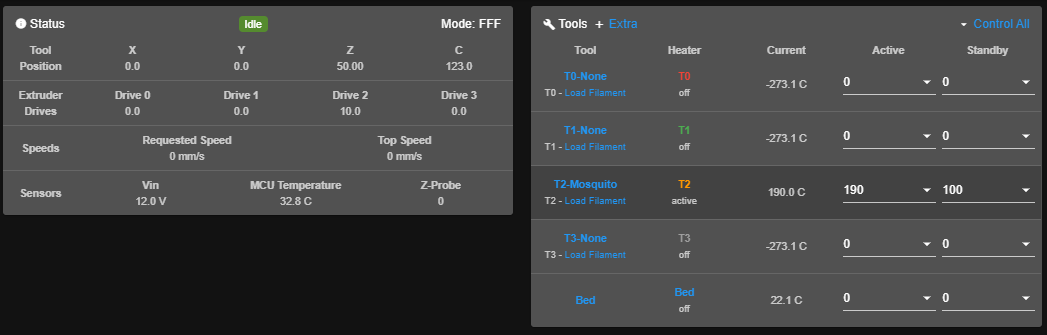
      I can select the Tool 2 in DWC and the Toolchanging sequence begins. I can check with ''T'' and get the status ''Tool 2 is selected''. Now I can heat up the hotend and than I hit ''Extrude'' in the Dashboard section of DWC. I instantly get the error message ''...no Driver 4 connected'' and that's correct because Tool 0 has no stepper connected yet but I've selected Tool 2 with the Driver 0 which has a stepper connected.

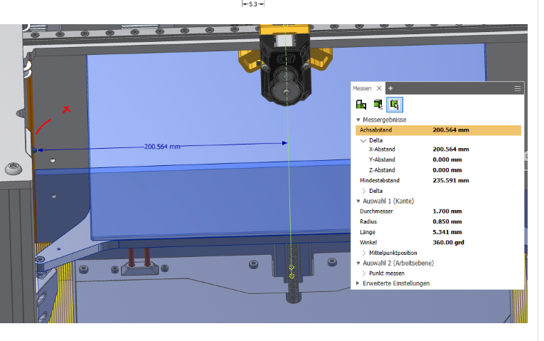
      What's strange as well I can't see the Tool 0 in DWC (left side of the picture):
      7bb930fb-6e93-4fb0-bf73-b49e06da9f86-image.png

      Thank you for your help.

      My Config.g file:

      ; General preferences-------------------------------------------------------------------------------------------------------------
      M111 S0 ; Debugging off
      G21 ; Work in millimetres
      G90 ; Send absolute coordinates...
      M83 ; ...but relative extruder moves
      M555 P2 ; Set firmware compatibility to look like Marlin
      M575 P1 B57600 S1 ;Set baud rate Duet Board.
      M575 P0 B57600 S1 ;Set baud rate USB

      ; Network------------------------------------------------------------------------------------------------------------------------------
      M550 P"CHANGER" ; Set machine name
      M552 S1 ; Enable Networking
      M586 P0 S1 ; Enable HTTP
      M586 P1 S0 ; Disable FTP
      M586 P2 S0 ; Disable Telnet

      ; Printer Type-------------------------------------------------------------------------------------------------------------------------

      M667 S1 ; Select CoreXY mode

      ; Steppers/Drives--------------------------------------------------------------------------------------------------------------------
      M584 X5 Y6 Z7:8:9 C2 E4:3:0:1 ; Assign motors to axes
      M569 P0 S1 ; Drive 0 goes forwards Extruder 2 (Tooldock D2)
      M569 P1 S1 ; Drive 1 goes forwards Extruder 3 (Tooldock D3)
      M569 P2 S0 ; Drive 2 goes backwards Coupler-Motor
      M569 P3 S1 ; Drive 3 goes forwards Extruder 2 (Tooldock D1)
      M569 P4 S1 ; Drive 4 goes forwards Extruder 1 (Tooldock D0)
      M569 P5 S0 ; Drive 5 goes backwards Y-Stepper
      M569 P6 S0 ; Drive 6 goes backwards X-Stepper
      M569 P7 S0 ; Drive 7 goes backwards Z1 motor left
      M569 P8 S0 ; Drive 8 goes backwards Z2 motor rear
      M569 P9 S0 ; Drive 9 goes backwards Z3 motor right

      M671 X200:0:-200 Y125:-200:125 S4 ; Lead screw positions , Snn Maximum correction allowed for each leadscrew in mm (optional, default 1.0)

      ; Endstops -----------------------------------------------------------------------------------------------------------------------------
      M574 X1 S1 P"xstop" ; Set X endstop (switch)
      M574 Y2 S1 P"ystop" ; Set Y endstop (switch)

      M574 Z0 P"nil" ; No Z endstop @used by DC42 using G30 homing
      M558 P8 C"zstop" H5 F120 T10000 A5 S0.01 ; Set Z probe type to switch
      G31 Z0 ; Set Z probe trigger value, offset and trigger height

      M557 X-145:145 Y-120:98 S30 ; Set Z probe: Define mesh grid

      M574 C1 S3 ; Stall detect coupler at low end of its range

      ; Stepper driver ---------------------------------------------------------------------------------------------------------------------
      M350 E16:16:16:16 I1 ; Configure E microstepping with interpolation
      M350 C8 I0 ; Configure C microstepping with interpolation
      M350 X16 Y16 Z16 I1 S2 ; Configure XYZ microstepping with interpolation

      M92 X80.3 Y80.3 Z1596 C100 E834:834:409:834 ; Set steps per mm
      M906 X1100 Y1100 Z1000 C400 E900:900:900:900 I30 ; Set motor currents (mA)
      M84 S120 ; Set idle timeout

      ; Stall Detection
      M915 C S3 F1 H400 R0 ; Coupler
      M915 X Y S3 F0 H400 R0 ; X / Y Axes

      ; Axis ------------------------------------------------------------------------------------------------------------------------------------
      M208 X-180.2:180.2 Y-125:139.65 Z0:280 C0:240 S0 ; Set axis maxima & minima
      M566 X300 Y300 Z20 C2 E100💯150:100 ; Set maximum instantaneous speed changes
      M203 X15000 Y15000 Z1200 C5000 E5000:5000:5000:5000 ; Set maximum speeds (mm/min)
      M201 X2500 Y2000 Z500 C500 E2500:2500:2500:2500 ; Set accelerations (mm/s^2)

      ; AAR ---------------------------------------------------------------------------------------------------------
      M593 F50 ; cancel ringing at 50Hz
      M376 H0 ; bed compensation taper, Ausschleichhöhe

      ; Bed and Tools

      ; >Heaters< ---------------------------------------------------------------------------------------------------------------------------

      ; Heatbed
      M308 S0 P"bedtemp" Y"thermistor" A"Bed" T100000 B4138 C0 ; Set thermistor
      M950 H0 C"bedheat" T0 ; Bed heater
      M140 H0 ; Add heater to bed after RRF3.01 RC10
      M143 H0 S120 ; Set temperature limit for heater 0 to 225C

      ; Tooldock D0
      M308 S1 P"e2temp" Y"thermistor" A"T0" T100000 B4138 C0 ; Set thermistor
      M950 H1 C"!exp.heater3" T1 ; Heater on E2 Heater
      M143 H1 S300 ; Set temperature limit for heater 1 to 300C

      ; Tooldock D1
      M308 S2 P"e3temp" Y"thermistor" A"T1" T100000 B4138 C0 ; Set thermistor
      M950 H2 C"!exp.heater4" T2 ; Heater on E3 Heater
      M143 H2 S300 ; Set temperature limit for heater 2 to 300C

      ; Tooldock D2
      M308 S3 P"e4temp" Y"thermistor" A"T2" T100000 B4138 C0 ; Set thermistor (Thermistor on E4)
      M950 H3 C"!exp.heater5" T3 ; Heater on E4 Heater
      M143 H3 S300 ; Set temperature limit for heater 3 to 300C

      ; Tooldock D3
      M308 S4 P"e6temp" Y"thermistor" A"T3" T100000 B4138 C0 ; Set thermistor
      M950 H4 C"!exp.heater6" T4 ; Heater on E5 Heater
      M143 H4 S300 ; Set temperature limit for heater 4 to 300C

      ; >Tools< -------------------------------------------------------------------------------------------------------------------------------

      ; Tooldock D0
      M563 P0 S"T0-None" D4 H1 F3 ; Define tool 0 (Tooldock D0)
      G10 P0 X0 Y0 Z0 ; Reset tool 0 axis offsets
      G10 P0 R0 S0 ; Reset initial tool 0 active and standby temperatures to 0C

      ; Tooldock D1
      M563 P1 S"T1-None" D3 H2 F4 ; Define tool 1 (Tooldock D1)
      G10 P1 X0 Y0 Z0 ; Reset tool 1 axis offsets
      G10 P1 R0 S0 ; Reset initial tool 1 active and standby temperatures to 0C

      ; Tooldock D2
      M563 P2 S"T2-Mosquito" D0 H3 F5 ; Define tool 2 (Tooldock D2), Drive 0 (P0) for Tooldock T2, Partcooling fan on Fan3 (Duex)
      G10 P2 X0 Y0 Z0 ; Reset tool 2 axis offsets
      G10 P2 R100 S210 ; Reset initial tool 2 active and standby temperatures to 210C and 100C

      ; Tooldock D3
      M563 P3 S"T3-None" D1 H4 F6 ; Define tool 3 (Tooldock D3)
      G10 P3 X0 Y0 Z0 ; Reset tool 3 axis offsets
      G10 P3 R0 S0 ; Reset initial tool 3 active and standby temperatures to 0C

      ; >Fans< --------------------------------------------------------------------------------------------------------------------------------
      M950 F0 C"e0heat" ; Air-Pump on E0-Heater-terminal
      M950 F1 C"e1heat" ; LED-Light on E1-Heater-terminal
      M950 F2 C"fan2" ; Exhaust-Fans (2 parallel) on Fan2 (Duet2_Wifi)
      M950 F3 C"duex.fan3" ; Partcooling Fan Tooldock D0
      M950 F4 C"duex.fan4" ; Partcooling Fan Tooldock D1
      M950 F5 C"duex.fan5" ; Partcooling Fan Tooldock D2
      M950 F6 C"duex.fan6" ; Partcooling Fan Tooldock D3
      M950 F7 C"!exp.heater7" ; Watercooling-Pump on E6-Heater (Duex5)
      M950 F8 C"fan0" ; Heatsink Fan Tooldock D0 on Fan0 (Duet2)
      M950 F9 C"fan1" ; Heatsink Fan Tooldock D1 on Fan1 (Duet2)
      M950 F10 C"duex.fan7" ; Heatsink Fan Tooldock D2 on Fan7 (Duex5)
      M950 F11 C"duex.fan8" ; Heatsink Fan Tooldock D3 on Fan8 (Duex5)

      M106 P0 S0 C"Airpump" ; Air-Pump
      M106 P1 S0 C"LED" ; LED LIGHT
      M106 P2 S0 C"Exhaust" ; Exhaust-Fans
      M106 P3 S0 C"PCF-T0" ; Partcooling Fan Tooldock D0
      M106 P4 S0 C"PCF-T1" ; Partcooling Fan Tooldock D1
      M106 P5 S0 C"PCF-T2" ; Partcooling Fan Tooldock D2
      M106 P6 S0 C"PCF-T3" ; Partcooling Fan Tooldock D3
      M106 P7 S0 C"Waterpump" ; Watercooling-Pump
      M106 P8 S0 C"Heatsink D0" ;
      M106 P9 S0 C"Heatsink D1" ;
      M106 P10 T50 H3 C"Heatsink D2" ;
      M106 P11 S0 C"Heatsink D3" ;

      ; Tools other settings -------------------------------------------------------------------------------------------------------------

      ; Linear Advance
      ;M572 D0 S0.2 ; pressure advance T0
      ;M572 D1 S0.2 ; pressure advance T1
      M572 D2 S0.04 ; pressure advance T2
      ;M572 D3 S0.2 ; pressure advance T3

      ; >Tool offsets G1 X318.1 Y0<
      G10 P0 X14.1‬0 Y-60 Z-7.60 ; T0
      G10 P1 X13.64 Y-60 Z-7.81 ; T1
      G10 P2 X10 Y-60 Z-5.33 ; T2 Mosquito, Bowden 1.75mm
      G10 P3 X-9 Y-50 Z-7.88 ; T3

      posted in General Discussion
      Chuckonelliundefined
      Chuckonelli
    • RE: Max. number of Fans, Duet2Wifi + Duex5

      @dc42 Thank you for your answer.

      I finally got it working. I'm not sure why it first didn't worked (I assume that I somehow did something wrong in the sequence of the commands earlier)

      Just for disclosure:

      M950 F0 C"e0heat" ; Air-Pump on E0-Heater-terminal
      M950 F1 C"e1heat" ; LED-Light on E1-Heater-terminal
      M950 F2 C"fan2" ; Exhaust-Fans (2 parallel) on Fan2
      M950 F3 C"duex.fan3" ; Partcooling Fan Tooldock D0
      M950 F4 C"duex.fan4" ; Partcooling Fan Tooldock D1
      M950 F5 C"duex.fan5" ; Partcooling Fan Tooldock D2
      M950 F6 C"duex.fan6" ; Partcooling Fan Tooldock D3
      M950 F7 C"!exp.heater7" ; Watercooling-Pump on E6-Heater (Duex5)
      M950 F8 C"fan0" ; Heatsink Fan Tooldock D0 on Fan0 (Duet2)
      M950 F9 C"fan1" ; Heatsink Fan Tooldock D1 on Fan1 (Duet2)
      M950 F10 C"duex.fan7" ; Heatsink Fan Tooldock D2 on Fan7 (Duex5)
      M950 F11 C"duex.fan8" ; Heatsink Fan Tooldock D3 on Fan8 (Duex5)

      M106 P0 S0 C"Airpump" ; Air-Pump
      M106 P1 S0 C"LED" ; LED LIGHT
      M106 P2 S0 C"Exhaust" ; Exhaust-Fans
      M106 P3 S0 C"PCF-T0" ; Partcooling Fan Tooldock D0
      M106 P4 S0 C"PCF-T1" ; Partcooling Fan Tooldock D1
      M106 P5 S0 C"PCF-T2" ; Partcooling Fan Tooldock D2
      M106 P6 S0 C"PCF-T3" ; Partcooling Fan Tooldock D3
      M106 P7 S0 C"Waterpump" ; Watercooling-Pump
      M106 P8 S0 C"Heatsink D0"
      M106 P9 S0 C"Heatsink D1"
      M106 P10 S0 C"Heatsink D2"
      M106 P11 S0 C"Heatsink D3"

      Thank you for the quick help.

      posted in General Discussion
      Chuckonelliundefined
      Chuckonelli