@r4ffersApologies for my late reply. Have been sick with the you know what virus.
I have not added that code to my config, I thought this pendant was plug and play. But I will check and see if that solves any issues.
@r4ffersApologies for my late reply. Have been sick with the you know what virus.
I have not added that code to my config, I thought this pendant was plug and play. But I will check and see if that solves any issues.
@rilot love the design and the additional display! Are you able to elaborate a bit on the wiring scheme as posted on thingiverse? Especially on what are the names referring to in the excel pic posted?
Conn LCD = connection to lcd panel
Conn sd = ?
Exp1 = ?
Exp2= ?
Would be greatly appreciated!
Yess!! Adding that code to the config.g indeed did the trick! It works like a charm now!!
Thank you Raffers and Dhusolo for the suggestion!
@r4ffersApologies for my late reply. Have been sick with the you know what virus.
I have not added that code to my config, I thought this pendant was plug and play. But I will check and see if that solves any issues.
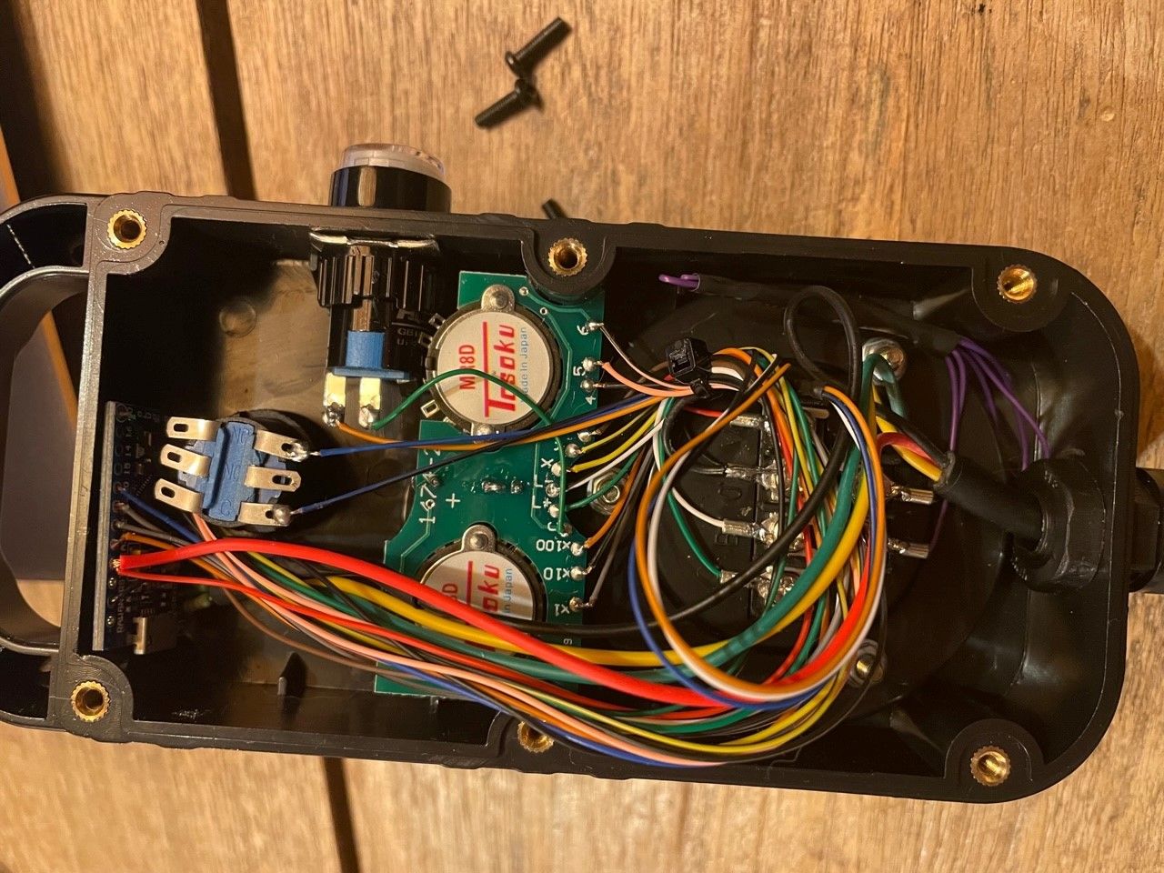
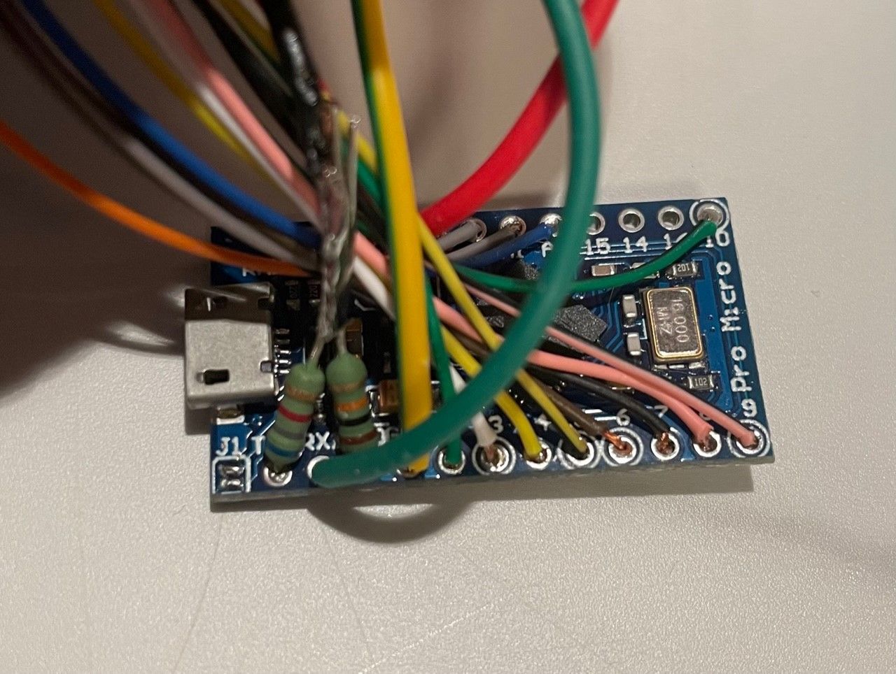
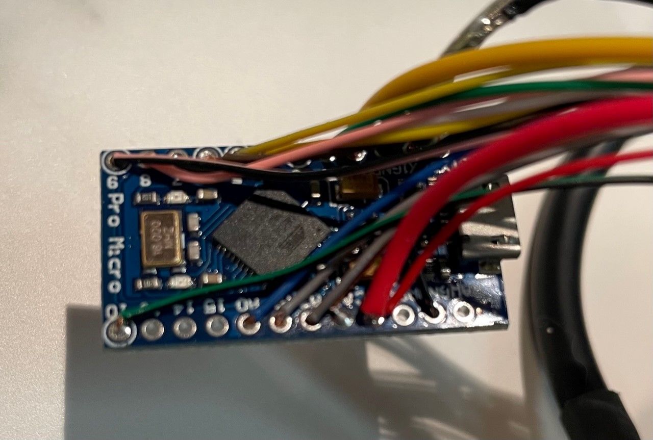
I checked/measured the wiring again, as far as I can see it is correct. The TX1 is connected via a 6.8K Ohm resistor to the URXD and the GND is connected via a 10K Ohm resistor to the URXD on the same wire as well (black in my world, blue in the original plan).
The only real difference I could find is that my pendant has 6 positions and I have connected the additional 2 (5 & 6) as well. Although this is in the plan as well, the colors of the wires differ, but that is it.
Apologies for the quality of the pictures, it was the best I could get


@unrepentantgeek Thank you. That is what I thought, so the port is correct. I already checked the comm line but will do so again.
Hi All!
As my title says I hacve a workbee with a duet2 wifi board, which I recently upgraded to RR 3.3 firmware (dated 2021-06-15). Over the past week I build a pendant for it using Davids guide and firmware. The build went without issues, I've used an arduino micro pro clone which gave me some problems as the IDE software (1.8.1.9) did not see it on my USB C port. But using my wife's macbook I got it working and was able to upload the firmware to the board, which it seems to have succesfully done.
I connected it to the duet2 paneldue port, and the led on the pendant nicely comes on and turns off when I hit the E-stop button on the pendant. But that is all it does.
I mean there is no magic blue smoke or anything and the cnc performs as it should. Jet the cnc ignores any input from the pendant. No matter what I set the switches to, no input seems to reach the machine. It doesnt respond to the E-stop, or input from the rotating switch. The console remains blank as well.
I checked the connections and all are correctly and there are no cable breaks or something as I can find. And as far as I know it is plug & play, so no changes/settings have to be made.
Does anybody have a clue in which direction I should be looking to fix this and getting to work?
Edit; just noticed that on the Duet2 board there are 2 panel due connections, one on the left (right next to Z probe) to which I connected the pendant. And the other one on the right of the board, which is labeled as Panel Due (Label:Conn_SD). Did I use the wrong port?
@cjm before I changed the frequency in the code I replaced the pwm board (just received the replacement). And presto it all worked!
So problem solved!
Thanks for all your input!
Thank you for your reply!
I have followed the guide from ooznest (https://learn.ooznest.co.uk/Guide/Connect+a+AMB+Kress+or+Mafell+spindle+with+digital+control/161). I have followed the guide to the letter and checked it to be correct.
So I am using the heater E0 for the PWM in and indeed it has been assigned as such by the firmware from ooznest. As I mentioned it nicely puts out a voltage between 0 & 10V depending on the commands inputted.
Which is done either by an input command (M3 …) or directly from the desktop control panel from ooznest where they have added preset buttons/macro’s.
Edit: just noticed in my first post the pwm in signal was corrected to “lemon”.. thx apple 
