@jay_s_uk You are totally right, I was questioning my sanity but I tried the same with a different driver and it worked now. I guess that my driver was broken. There were also some software issues.Thanks everyone for your help!
Best posts made by Kruix
-
RE: Connection issues to external Closed Loop Stepper Driverposted in Duet Hardware and wiring
Latest posts made by Kruix
-
RE: New Kinematics 3RRR Scaraposted in Firmware developers
@dc42
The MotorStepsToCartisian is a forward kinematic, is that function necessary to implement for testing? -
New Kinematics 3RRR Scaraposted in Firmware developers
Hello, I would like to implement the firmware for a 3RRR Scara,
which uses 3 Arms/Motors to set the XY position.
is there an easy way to test the kinematic from a function that outputs the coresponding angles from the backward transformation? ie.
The function outputs the angles for the motors from (0,0) after Homing.vector<double> CalculateAngles(double x, double y, double rot, double l1, double l2, double R, double r) { double pi=3.14159265358979; vector<double> phi= {7*pi/6, 11*pi/6, pi/2}; vector<double> my= {pi/6, 5*pi/6, 3*pi/2}; vector<double> E= {0, 0, 0}; vector<double> F= {0, 0, 0}; vector<double> G= {0, 0, 0}; vector<double> K= {0, 0, 0}; vector<double> theta= {0, 0, 0}; for(int i=0; i<3;i++){ E[i] = -2*l1*(y+r*sin(rot+phi[i])+R*sin(my[i])); F[i] = -2*l1*(x+r*cos(rot+phi[i])+R*cos(my[i])); G[i] = pow(x+r*cos(rot+phi[i])+R*cos(my[i]),2.0)+ pow(y+r*sin(rot+phi[i])+R*sin(my[i]),2.0)+pow(l1,2.0)-pow(l2,2.0); K[i] = sqrt(pow(E[i],2.0)+pow(F[i],2.0)-pow(G[i],2.0)); theta[i] = 2*atan2((-E[i]+K[i]),(G[i]-F[i])); } vector<double> theta_temp =cart2threeRRR(0,0,rot,l1,l2,R,r); theta[0]=theta[0]-theta_temp[0]; theta[1]=theta[1]-theta_temp[1]; if(theta[2]>3){theta[2]=theta[2]-2*Pi;} theta[2]=theta[2]-theta_temp[2]; return theta; -
RE: Connection issues to external Closed Loop Stepper Driverposted in Duet Hardware and wiring
@jay_s_uk You are totally right, I was questioning my sanity but I tried the same with a different driver and it worked now. I guess that my driver was broken. There were also some software issues.Thanks everyone for your help!
-
RE: Connection issues to external Closed Loop Stepper Driverposted in Duet Hardware and wiring
@jay_s_uk
The question was because of the article in https://docs.duet3d.com/User_manual/Overview/Getting_started_Duet_3_MB6XD
that states at the bottom that
"The Step, Dir and Enable outputs from the 6XD are either low (when "on") or floating/high impedence when "off". "
thats why I assumed the R command would only refer to the Polarity of the Enable Pin -
RE: Connection issues to external Closed Loop Stepper Driverposted in Duet Hardware and wiring
@T3P3Tony
Is it possible to set the STEP/DIR Signal itself active High instead of pulling it to ground? -
RE: Connection issues to external Closed Loop Stepper Driverposted in Duet Hardware and wiring
@T3P3Tony
Firstly thanks for the support!
changing the Polarity didn't work. But one more question, if there is no error signal of a motor, nothing needs to be connected there, right?
What Polarity does the jumper change? Is the standard active high or low? -
RE: Connection issues to external Closed Loop Stepper Driverposted in Duet Hardware and wiring
@dc42 It didnt work with 1k or 500ohms pullup resistors
-
RE: Connection issues to external Closed Loop Stepper Driverposted in Duet Hardware and wiring
@dc42
I will try that out, thank you.
Is the wiring correct with?
EN -EN
STEP - STEP
DIR -DIR
GROUND -GROUND
or should it be connected like the polulu in the image above? -
RE: Connection issues to external Closed Loop Stepper Driverposted in Duet Hardware and wiring
@dc42
Thank you for the reply.
Datasheet:
https://henschel-robotics.ch/wp-content/uploads/2022/04/Manual_HDrive.pdf
Model: 17ETH-i
Configuration:
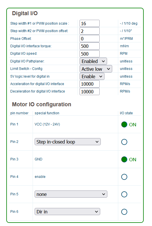
I have tried to use the Motor in the active high and active low configuration before.
I have found that the Signal voltage when the Motors where connected was pretty low (Amplitude of 0.8V)even when I have set the setting in the duet active high and also tried using 10k pullups to 5V
For me it looks as if it wasn't optically isolated as there are only 4 ESDG wires
I have also tried to crosswire like in the image:
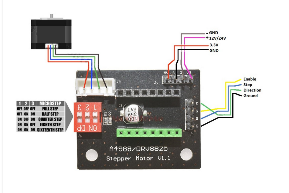
as in https://docs.duet3d.com/User_manual/Connecting_hardware/Motors_connecting_external
The Firmware is Reprap the latest stable version for Duet and
The Board is run over a Raspberry Pi 3B connected with an external 5V power supply and connected over the Serial cables.
The USB is not connected.