Duet3D Logo Duet3D
    • Tags
    • Documentation
    • Order
    • Register
    • Login
    1. Home
    2. TQKez 0
    • Profile
    • Following 0
    • Followers 0
    • Topics 7
    • Posts 19
    • Best 1
    • Controversial 0
    • Groups 0

    TQKez 0

    @TQKez 0

    1
    Reputation
    4
    Profile views
    19
    Posts
    0
    Followers
    0
    Following
    Joined Last Online

    TQKez 0 Unfollow Follow

    Best posts made by TQKez 0

    • What is a 'tool' in CNC according to RepRap in CNC world?

      So I've noticed that most of the post programs seem to assign different end mills to different 'tools' T1, T2 etc.
      But in the config a tool is not a cutter, but the spindle itself.

      This obviously causes errors about tools not being defined.

      So what is the correct way to deal with this?

      Am I supposed to define as many tools as I can ever imagine needing to change all with the same definition?

      ; CNC Mode
      M950 R0 C"fan0" L24100			; Create spindle index 0, with PWM pin on fan0 and 24000 RPM achieved at full PWM
      M563 P1 S"Spindle T1" R0 		; Create tool 1 with spindle 0 and call it "Spindle T1"
      M563 P2 S"Spindle T2" R0 		; Create tool 2 with spindle 0 and call it "Spindle T2"
      M563 P3 S"Spindle T3" R0 		; Create tool 3 with spindle 0 and call it "Spindle T3"
      ...
      ...
      M453
      
      posted in CNC
      TQKez 0undefined
      TQKez 0

    Latest posts made by TQKez 0

    • RE: How to find which line throws an error?

      @dc42

      Still struggling with this. Just can't work it out. I'm not using mesh levelling (at least I've never enabled it intentionally and I don't see anything related to it in my configs)

      ;Run the Z Probe at the current position
      M291 P"Probing to find Z=0" S0 T2
      G90 G0 Z30 			; Quick move down to Z30. (Comment this out for long drill bits)
      M208 Z-10 S1		; Temporarily allow negative movement
      G30 Z-205			; Single Z Probe. (Descend slowly untill the probe is triggered)
      M208 Z0 S1			; Dissallow negative movement
      G1 H3 Z205 F360		; Move Z up stopping at the endstop and set Z maximum to current position.
      M208 Z-0.75 S1		; Allow slight negative movement for drilling etc
      

      This is my Z-Probe Macro which I just ran to make 0 the top of the spoils board.

      In this Job I have the final contour pass set to go -0.1 to make sure it goes all the way through and skims the spoils board by a hair.

      Ran the job and it quits at line 1380 with this as usual.

      Error: in GCode file line 1380: G1: target position outside machine limits
      
      1379 G1 X144.661 Y19.888
      1380 G1 Z-0.1 F250
      1381 G1 X144.527 Y20.25 F1920
      

      Given that my probe macro just set Z axis minimum to -0.75, why is it triggering this error?

      What common can I issue to the console to check what Z axis minimum is actually set to to check if its working?

      EDIT:

      Could it have something to do with Tool Change?
      Even though Fusion360 free wont combine multiple tool operations into a single NC program, this operation is still technically tool 5 in the list so the post processor is including a T5 command at the beginning of this program.

      Could that be wiping out my M208 minimum?

      I dont see anything in the Duet or Reprap docs about whether M208 is applied per tool, or globally.
      If it is per tool, how would one set it for every tool?
      posted in CNC
      TQKez 0undefined
      TQKez 0
    • RE: Any way to hide columns in the job list?

      @droftarts Hey there. I'm on 3.4.6 as that seems to be the latest still on the git hub page.
      I'd have to assume then that 3.5.0-rc1 is a nightly build.
      How can I find it?

      posted in Duet Web Control
      TQKez 0undefined
      TQKez 0
    • RE: Any way to hide columns in the job list?

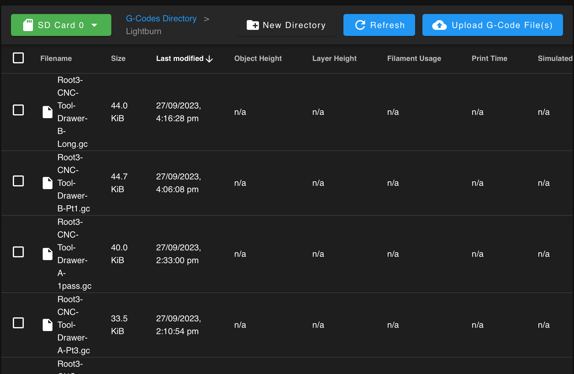
      Screen Shot 2023-09-29 at 7.31.54 am.png

      Here's an image to illustrate to problem on a laptop screen.
      All that really matters is the Job Filename, but there's so many extraneous columns, the poor filename is forced onto 6 barely readable hyphenated lines.

      posted in Duet Web Control
      TQKez 0undefined
      TQKez 0
    • Any way to hide columns in the job list?

      There are so many irrelevant columns in the Job page (for laser mode) that the filenames are squished and forced to one word per line. Not very readable.

      Is there a way to choose what columns are displayed to make some room for the important stuff?

      posted in Duet Web Control
      TQKez 0undefined
      TQKez 0
    • RE: Correct way to setup dust extractor

      @jay_s_uk said in Correct way to setup dust extractor:

      @TQKez-0 M7 isn't supported by RRF, but you can add support for it yourself.
      just create a file called M7.g and put it in sys, with whatever you want to happen as its contents.
      Then, when M7 is called, the contents of that file will be processed.

      Oh thats great!

      posted in CNC
      TQKez 0undefined
      TQKez 0
    • Correct way to setup dust extractor

      So I managed to repurpose an industrial wet/dry vacuum I had here that had a broken switch.
      I removed the switch and put a relay board in its place and have the trigger set via spare exp.heater4/5 assigned to fans F4/F5.

      At the moment, I'm just triggering it on and off with a macro and that works great.
      I'm guessing there's a 'proper' way to have this switching on at the right times though.

      e.g in the Ultimate RepRap Post-Processor script, I can see this which appears it would issue an M7 command

      // dust collector is not in use. If got a controlled one, uncomment below
      // if (properties.useDustCollector) {
      // writeBlock(mFormat.format(7)); // turns on dust collector
      // }
      

      Google that I can see it's usually used for coolant, but similar use case so appropriate enough.

      Is M7 the standard way dust/chip extractors are activated?
      If so how would I tell the Duet that my dust extractor is activated by switching on a fan (F4 in my case)?

      posted in CNC
      TQKez 0undefined
      TQKez 0
    • RE: The ULTIMATE RepRap Post-Processor for Fusion 360

      @bruce This is much better than other Fusion PP's I've experimented with, but I have the same problem as I do with all the the Fusion post processors in that it tries to do the first move into position without lifting the spindle.

      Once it gets to the first ramp down position, it moves the spindle up first before plunging, but it's already too late as it's crashed into the stock on the move and snapped the end mill.

      Not so hard to fix manually by inserting the appropriate move command just before the first G0, but its easy to forget.

      Is there a setting I'm missing that would make raise the spindle first (ideally to Z Max, and ideally also after a tool change) by first moving the spindle up and out of the way of the stock and clamps.

      Thanks.

      posted in CNC
      TQKez 0undefined
      TQKez 0
    • RE: NEJE N40630 lasermodul with Duet Wifi

      Actually I think I figured it out now. Works fine without the 74HCT02 board.

      Was a little confusing as there are some outdated threads here and the wiki needs updating.

      For testing the laser PWM, M452 laser mode with M571 to fire the laser as per the instructions in the wiki doesn't seem to work.

      So for anyone coming back here, this works for Neje lasers, with external 12V power, and the laser PWM connected directly to ext.heater3.

      Board: Duet 2 WiFi (2WiFi)
      Firmware: RepRapFirmware for Duet 2 WiFi/Ethernet 3.4.1rc1 (2022-05-03)

      In config.g

      ;M452 C"exp.heater3" R255 F500  ; Laser Mode (disabled for testing)
      
      ;Setup laser for testing on heater3 pin, PWM frequenxy 500 (this number isn't too important for this laser)
      M950 P7 C"exp.heater3" Q500 ;
      

      Testing examples.

      M42 P7 S0.01	; Test laser at 1% power. This reads 001 on the Neje LED display.
      M42 P7 S0.10	; Test laser at 10% power. This reads 010 on the Neje LED display.
      M42 P7 S0	; Turn off laser. This reads 000 on the Neje LED display and shuts down the laser and fan.
      

      Once happy with PWM is working properly, swap to using real laser mode.

      M452 C"exp.heater3" R255 F500  ; Enable Laser Mode.
      
      ;Setup laser for testing on heater3 pin, PWM frequenxy 500 (this number isn't too important for this laser)
      ;M950 P7 C"exp.heater3" Q500 ; Test mode (disabled)
      

      With laser mode enabled, the laser should fire automatically with G1 commands with S parameter setting laser power.

      posted in Laser Cutters
      TQKez 0undefined
      TQKez 0
    • RE: NEJE N40630 lasermodul with Duet Wifi

      @o_lampe

      Sorry, by 'board' I meant the circuit containing the 74HCT02 Quad NOR Gate which is said to be necessary in the Duet Wiki.

      I'm definitely using the Neje board with the LED and test switch. It just doesn't seem respond to any PWM changes when following the instructions in the wiki.

      I'm running the Duet at 24V as this machine is usually set up as a CNC and its better for the steppers.
      Then I have a 24-12V buck converter powering the laser which works fine in test mode.

      @o_lampe said in NEJE N40630 lasermodul with Duet Wifi:

      I'd use a 5V fan port to fire the laser, or if you run the Duet board with 12V, you can jumper the fan port to 12V too.

      So the Wiki says to use heater3 and I've seen other recommendations to use the heater pins for PWM.
      So you would say use a fan instead?

      Thanks.

      posted in Laser Cutters
      TQKez 0undefined
      TQKez 0
    • RE: NEJE N40630 lasermodul with Duet Wifi

      I also need some clarification regarding the Neje line of lasers.
      I got the E40 which is higher output but the same PWM configuration.

      I followed the instructions here, including building the board.

      https://duet3d.dozuki.com/Wiki/Laser_PWM_control

      But the PWM signal doesn't seem to work.
      It's unclear whether the board is actually necessary with this module. The wiki page says the Duet Wifi 2 won't be able to drive the laser PWM directly, but it does not state why.

      According to the Neje docs, the PWM signal can take anything up to 12V, but the 'ON' state is activated by anything over 2.5V. So in theory, a 3.3V, 5V, or anything up to 12V should just work the way I understand it.

      Does this mean the board is unnecessary and we can drive the Neje PWM directly from the Duet board?

      https://neje99.com/tutorial/how-to-use-laser-modules.html
      https://neje99.com/faq/how-to-make-laser-module-work-with-your-control-board.html
      https://neje99.com/faq/about-pwm-signal-specification.html

      Thanks in advance!

      posted in Laser Cutters
      TQKez 0undefined
      TQKez 0