Improving Print quality at high speed
-
Hi guys,
I´m looking for some advice to further improve my print quality (at higher speeds)
First shortly, this is my printer, it is a custom system with dual super whopper on the X and a 180W servo on the Y axis.
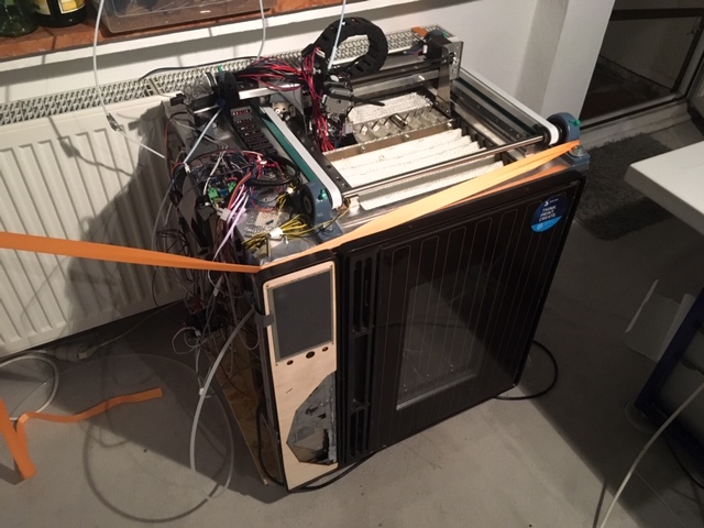
I have originally built it for the Solvay AM cup to print PPSU in the 230°C heated chamber.
I´ve recently started tuning this for better performance. It is a fairly heavy system (the printer weighs ~50kg) and i´ve strapped it to my radiator to increase the effective weight and dampening
I converted the bowden to a "direct" drive (ca. 100mm bowden).
Did some tests with pressure advance and got good results with around 0.55. (I had to reduce this to 0.25 after the DAA adjustment for some reason)
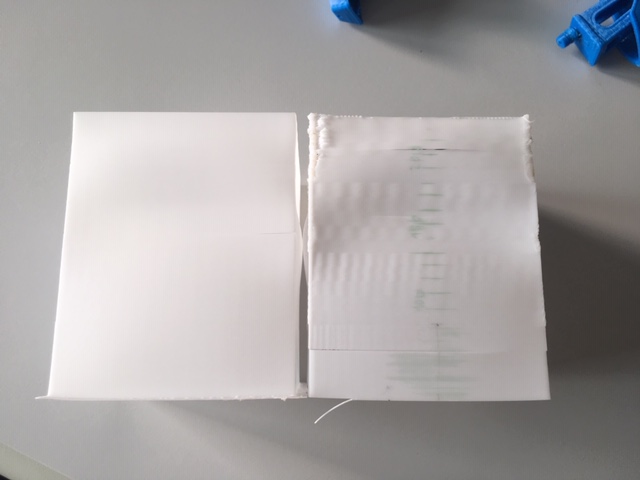
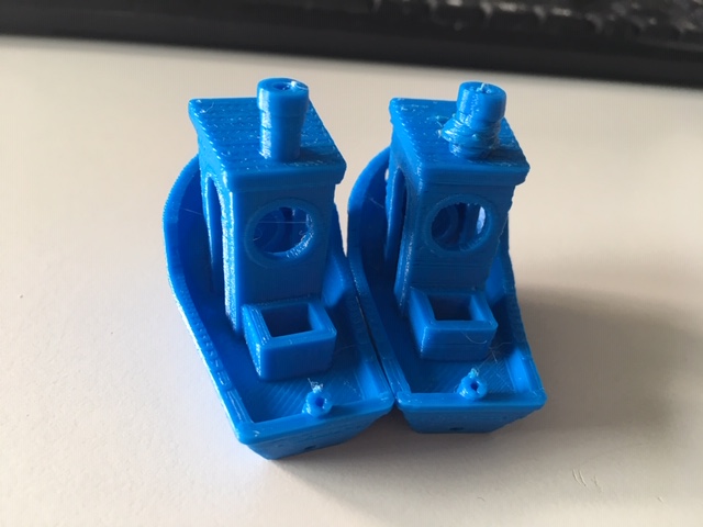
Then i started tinkering with the M593 Dynamic Acceleration Adjustment feature and found good cancellation at 24.5 Hz.Right is without DAA and PA, left is with M593 D0 S24.5 and M572 D0 S0.25.
The test tower was printed at 50,100,150 and 200 mm/s, with each speed separated into 5 acceleration zones from between 1000 and 5000 mm/s². Jerk was set to 100 for testing.
Now for the real print tests:
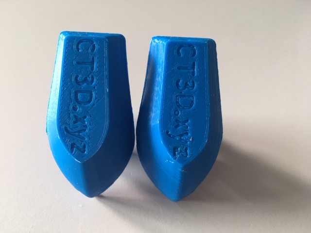
the two benchys were printed at 40 and 100 mm/s, both with accelerations of 5000mm/s² and XY jerk 500. Stratasys ABS at 270C, and 90C chamber temperature. Left is slow (print time 1h 11m), right is fast (print time 44m)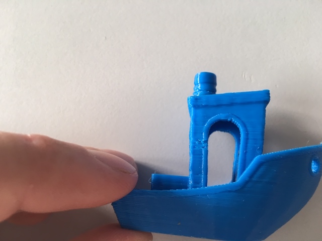
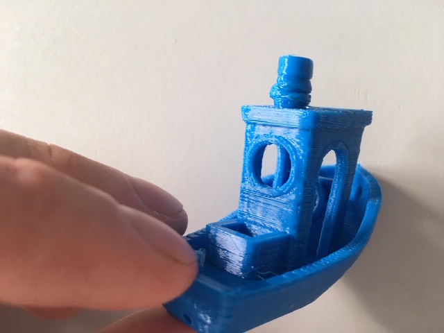
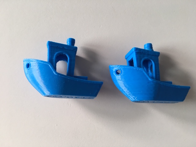
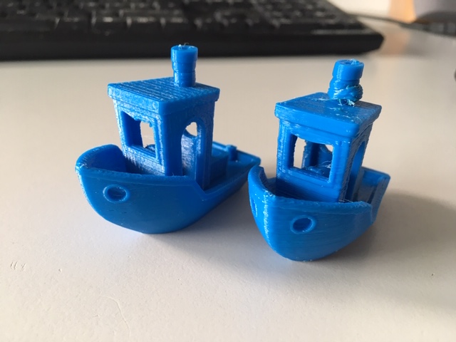
I´m not really concerned with the ringing, i have some changes to make to my Z axis. My concern is with the inconsistent layering especially around the window pillar area. They dont stack on top of each other so consistently. Also the chimney, it creates a crazy blob where i don´t really know where it comes from.
My suspicion is with the extruder/ hotend. I can always see the bowden tube move a bit while retracts/unretracts and with the PA. It creates elasticity. Also the fixing in the heatsink where the capricorn tube attaches to moves a bit up and down creating a bit of backlash.
Could it also be overheating?
I´m hoping for any advice.Thank you
Max -
@nitrofreak said in Improving Print quality at high speed:
Could it also be overheating?
Absolutely. The plastic doesn't have time to cool before the next layer is laid down and it flexes and moves along with the nozzle making it look messy and blobby.
The benchy is a fine little test model, but not really designed to print so fast. Try scaling it up 2 or 3x and print again.
-
@phaedrux Thanks, I´ll check. Maybe I´ll try printing two side by side instead of 200%.
I´ll also have to try the "print islands sequentially without optimization" option, maybe that helps?
Anything else that could cause the uneven layer stacking? I´ve tightened my belts quite well, could probably play the violin on them. -
Well if the uneven layers existed on both prints if be more inclined to think it was mechanical, but such a small model printed so fast will exhibit heat issues that mask other issues.
-
Ok so I´ve had a suspicion. i printed a 31.8mm circle (100mm circumference) at 100mm/s in vase mode to see the layer cooling (1 layer/sec)
Then i noticed something unusual:

Here is a video:
https://www.youtube.com/watch?v=tMfIscR2lI0&feature=youtu.be
the left one i printed the first part at 30mm/s, the last part at 20mm/s, in between at above 100mm/s.
I turned off all other features like DAA and PA to exclude those sources of error, but it had no effect.
It produces a really jerky movement. I went through the troubleshooting sitehttps://duet3d.dozuki.com/Wiki/Jerky_movement_when_printing
but nothing worked. I even tried XY Jerk set at 2000. Extruder jerk is set at 1500.
Here is my config:
; Drives
M569 P0 S1 ; Drive 0 goes forwards (X1)
M569 P1 S1 ; Drive 1 goes forwards (X2)
M569 P2 S0 ; Drive 2 goes backwards (Z)
M569 P3 S1 ; Drive 3 goes forwards extruder
M569 P4 S0 ; Drive 4 goes backwards extruder 2
M569 P5 S0 T3 ; Drive 5 minimum step pulse timing 3 microseconds (JMC servo minimum 2.5 microseconds)
M584 X0:1 Y5 Z2 E3:4 ; Apply custom drive mapping
M350 Y1 Z64 ;E16:16I0 ; Configure microstepping without interpolation
M350 X16:16 I1 E16:16 I1 ; Configure microstepping with interpolation
M92 X88.89 Y360.00 Z3200.00 E434:400 ; Set steps per mm, mk8 extruder 94.3
M566 X600.00 Y600.00 Z12.00 E1500.00:200.00 ; Set maximum instantaneous speed changes (mm/min)
M203 X18000.00 Y18000.00 Z2000.00 E4200.00:4200.00 ; Set maximum speeds (mm/min)
M201 X5000.00 Y5000.00 Z50.00 E2000.00:1000.00 ; Set accelerations (mm/s^2)
M906 X1600.00 Y800.00 Z800.00 E700.00:700.00 I30 ; Set motor currents (mA) and motor idle factor in per cent
M593 F24.5
M84 S30 ; Set idle timeoutHere is a snippet of the gcode:
G1 X104.199 Y225.846 Z37.800 E0.0328 F6000
G1 X103.964 Y226.179 Z37.802 E0.0491
G1 X103.463 Y226.831 Z37.802 E0.0819
G1 X102.929 Y227.457 Z37.804 E0.1148
G1 X102.653 Y227.756 Z37.806 E0.1310
G1 X102.071 Y228.338 Z37.807 E0.1639
G1 X101.461 Y228.887 Z37.808 E0.1966
G1 X100.822 Y229.404 Z37.810 E0.2294
G1 X100.158 Y229.887 Z37.812 E0.2622
G1 X99.470 Y230.334 Z37.813 E0.2949
G1 X98.758 Y230.745 Z37.815 E0.3277
G1 X98.025 Y231.118 Z37.817 E0.3606
G1 X97.656 Y231.289 Z37.818 E0.3768
G1 X96.895 Y231.603 Z37.819 E0.4096
G1 X96.122 Y231.878 Z37.821 E0.4424
G1 X95.334 Y232.111 Z37.822 E0.4752
G1 X94.536 Y232.302 Z37.824 E0.5080
G1 X93.729 Y232.452 Z37.826 E0.5407
G1 X92.914 Y232.559 Z37.827 E0.5735
G1 X92.096 Y232.624 Z37.829 E0.6063
G1 X91.275 Y232.645 Z37.831 E0.6390
G1 X90.453 Y232.624 Z37.833 E0.6719
G1 X90.046 Y232.597 Z37.834 E0.6881
G1 X89.228 Y232.511 Z37.835 E0.7210
G1 X88.417 Y232.383 Z37.837 E0.7537Then i tried the same circle scaled to 400% and printed that at 250 mm/s and that worked fine. the bad parts are when i tried pushing it to 300mm/s and it barfed, it started to accelerate and decelerate down to 140mm/s partly. Maybe the Processor was overloaded by that. I think the layering inconsistencies at the higher Z values come from the wobbly print. It is single wall after all, and had the inconsistent layers in between.
Here is a video of that:
https://www.youtube.com/watch?v=o-Qg3nTha1A&feature=youtu.be


Here is a snippet of the gcode from that:
G1 X55.946 Y115.177 Z22.800 E0.0663 F6000
G1 X57.472 Y114.521 Z22.801 E0.1326
G1 X59.015 Y113.905 Z22.802 E0.1989
G1 X60.574 Y113.330 Z22.802 E0.2652
G1 X62.146 Y112.796 Z22.803 E0.3315
G1 X63.733 Y112.304 Z22.804 E0.3978
G1 X65.332 Y111.853 Z22.805 E0.4641
G1 X66.942 Y111.444 Z22.806 E0.5304
G1 X68.562 Y111.077 Z22.807 E0.5967
G1 X70.191 Y110.753 Z22.808 E0.6630
G1 X71.828 Y110.472 Z22.808 E0.7293
G1 X73.472 Y110.234 Z22.809 E0.7956
G1 X75.122 Y110.038 Z22.810 E0.8619
G1 X76.776 Y109.886 Z22.811 E0.9282
G1 X78.434 Y109.778 Z22.812 E0.9945
G1 X80.094 Y109.712 Z22.812 E1.0608
G1 X81.755 Y109.691 Z22.813 E1.1271
G1 X83.416 Y109.712 Z22.814 E1.1934
G1 X85.076 Y109.778 Z22.815 E1.2597
G1 X86.734 Y109.886 Z22.816 E1.3260
G1 X88.387 Y110.038 Z22.817 E1.3923
G1 X90.037 Y110.234 Z22.817 E1.4586
G1 X91.682 Y110.472 Z22.818 E1.5249
G1 X93.318 Y110.753 Z22.819 E1.5912
G1 X94.948 Y111.077 Z22.820 E1.6575
G1 X96.568 Y111.444 Z22.821 E1.7238
G1 X98.178 Y111.853 Z22.822 E1.7901
G1 X99.777 Y112.304 Z22.823 E1.8564Any idea?
-
I´ve printed another circle vase at 250% and tried to push it to 250mm/s as well like the big one, and it didn´t work. the max was at ~192 mm/s. It doesn´t like the 1 revolution per second.
So it points to something like the jerk setting being too low to change the direction fast enough. But i can´t believe that, as even when i increase it further beyond 4000, the speed limit stays the same. -
How have you sliced it? Is there a minimum layer time set or a volumetric extrusion limit?
-
Sliced in S3D, there are no limits that i set. the export settings from the CAD file are also reasonably fine; 0.05mm resolution and 1.5 degree angles.
Fairly standard settings, 0.4 nozzle, 0.2 layer height.
Where does one set a volumetric extrusion limit? -
@nitrofreak said in Improving Print quality at high speed:
Where does one set a volumetric extrusion limit?
It exists in Slic3r, not sure if S3D has anything similar.
Can you try printing it with 2 walls instead of vase mode? Or a different slicer if you have one configured.
-
Ok so i´ve printed the 100mm circumference again with 2 perimeters and without vase mode.
And crazy, it works. None of the jitter from before. I tried at 30 (for comparison), 100 and 150mm/s.
The faster ones almost look better than the 30mm/s version.
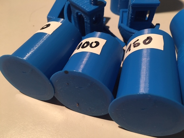
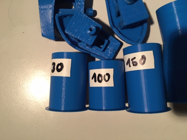

 !
!I also tried the print at 200mm/s and it seems my servo did not like that. when it was set to 200, it did a very consistent shift. It almost looks like the pulley was slipping, but i checked everything and it was fine.
2_1564354658120_IMG_5227.JPG
Here is a video of the 200mm/s part.
https://www.youtube.com/watch?v=0UBmucWow6o
I´m curious as to why that geometry at that speed causes that behaviour, since both higher speeds and higher acceleration did never cause that behaviour.I wonder why the vase mode from S3D would cause that behaviour. Could it be because of the fairly conservative Z jerk and acceleration ?
-
@nitrofreak said in Improving Print quality at high speed:
I wonder why the vase mode from S3D would cause that behaviour. Could it be because of the fairly conservative Z jerk and acceleration ?
That would be my guess. Test slicer and Cura.
I tend to run 60 z jerk and high extruder jerk. But I also don't print at such high speeds. I think that is probably limiting you.
-
Ok i got it.
It was definitely the Z jerk and/or acceleration.This cylinder was printed in vase mode at 100mm/s minus the lower part where there is the temperature artefact, i tried to push it to 150mm/s but that was definitely too hot, since that resulted in a layer time of 0.66 seconds.
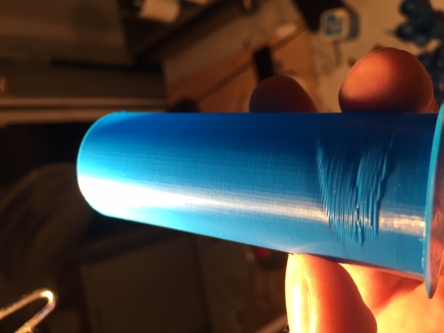
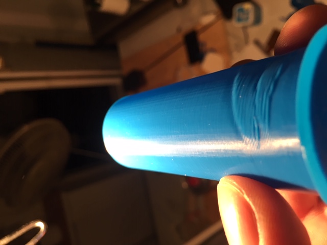
The layers look really nice. However i still notice these small vertical lines in the print.
What could these come from? they are longer than the segments in g-code, so it probably isnt that.
I may try to write a gcode with G2/G3 arc moves and see how much difference that makes.
If it´s still the same, could it be the belts? -
@nitrofreak said in Improving Print quality at high speed:
they are longer than the segments in g-code, so it probably isnt that.
What's the segment size?
I notice similar vertical bands sometimes with cylindrical sections.
-
@phaedrux said in Improving Print quality at high speed:
@nitrofreak said in Improving Print quality at high speed:
they are longer than the segments in g-code, so it probably isnt that.
What's the segment size?
I notice similar vertical bands sometimes with cylindrical sections.
in the Gcode the segments are more or less 0.2mm, in the print they are more like 0.6 to 1mm