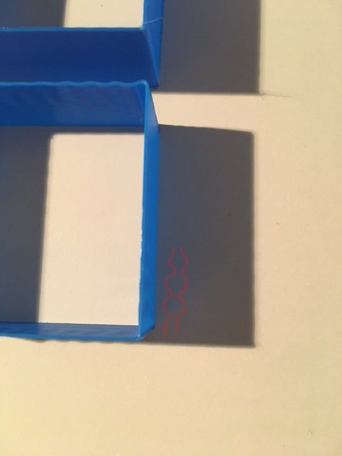
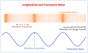
i have noticed that, while printing fast, different patterns in X and Y start appearing. the patterns on the print wall parallel to the Y axis resemble that of a longitudinal wave, while the pattern parallel to the X axis resembles a transverse wave. I hope one can see the compression and stretching in this pic. I added the sketch to make it easier to visualize.
The transverse wave is easy to see in the top, horizontal aprt of the print.
After thinking it could only come from the bed, where the plates that hold the bed are only 2mm titanium and can flex in the Y axis. Unfortunately this is also the direction in which the heavier gantry rides, further amplifying the paper stiffness problem.
I already had plans of replacing that 2mm titanium with some 6mm stainless steel, but i ran into problems. Also, this would only reduce the problem, not totally eliminate it.
Active damping the bed is not easy due to the chamber temperature, adding another guide is also impossible due to space restraints.
This video inspired me:
https://www.youtube.com/watch?v=Ofg21LDNxdU&list=PLV4isz0nRXU3GnEECwNQKYsIve-Zo85Ks&index=39&ab_channel=RogierdeHaan
I wanted to see if this would work in the real world. I am very aware of the force cancellation test that deckingman made, however i saw some flaws.
- He ran very low acceleration and jerk settings (like 500mm/s²) so there was nothing to really exacerbate the effect and no way to be able to easily see it.
- the cancellation weight was on the wrong plane. He assumed the frame to be infinitely stiff, and the floor make a pivot point around which the higher up position of the cancel gantry would cancel out the forces from the print gantry due to the lever effect. However i believe those assumtions are not valid.
So, after some thinking i came up with a dynamic force cancellation design of my own.
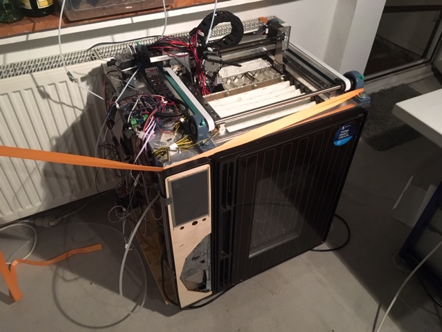
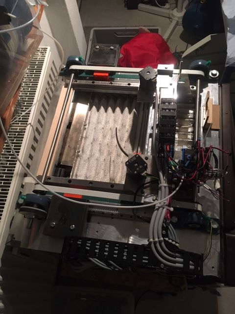
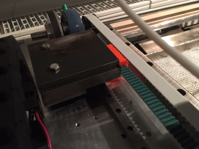
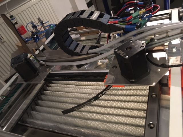
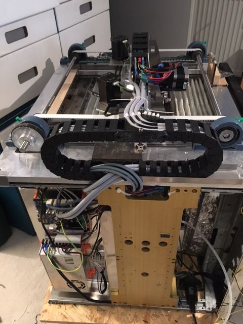
Fortunately i built a basic cartesian machine with separate belts for X and Y. So i tapped directly into the "returning" belt path. I installed two MGN12 rails onto which i bolted 3kg of steel each. 6kg is roughly what my gantry weighs. I gave it my best effort to make the center of gravity of the steel weights the same height as the gantry.
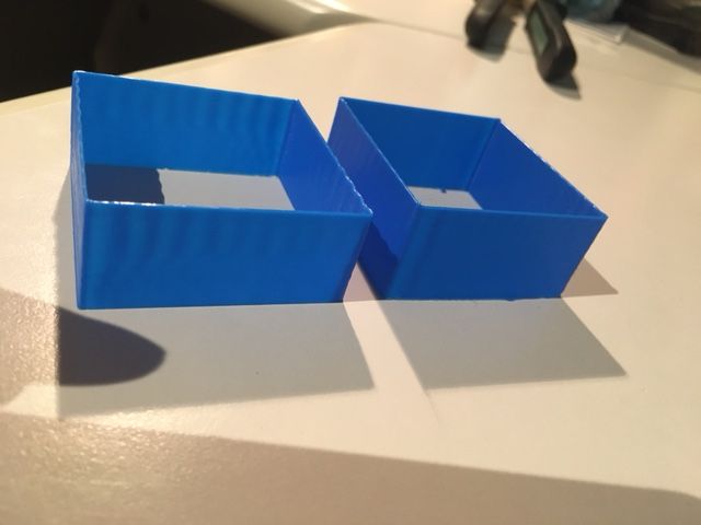
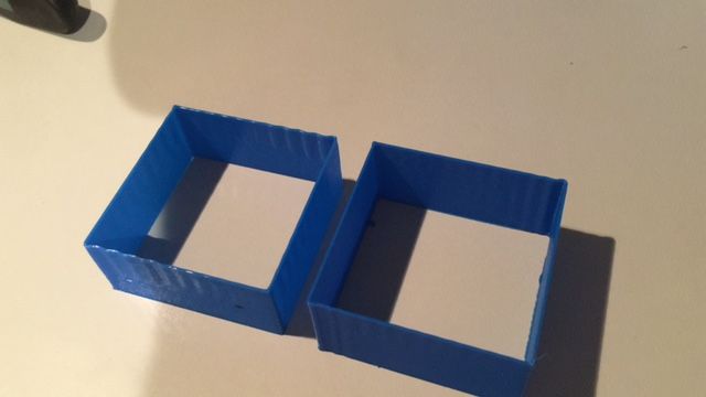
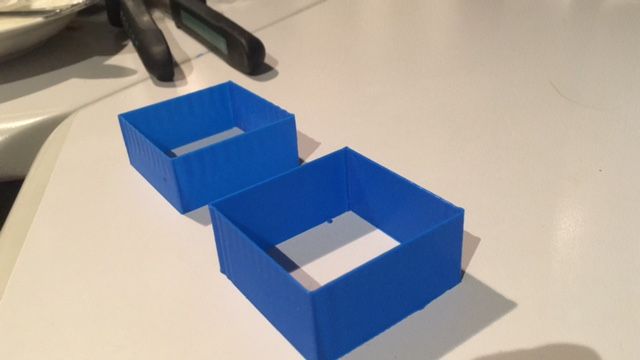
Here are the tests. Same Gcode, on the left without and on the right with the weight.
It is a 60mm cube with only 1 perimeter, normal print, no vase mode ( to exclude artifacts caused by the Z axis)
Print speed 100mm/s, jerk 100mm/s (yes, that is right) acceleration 5000mm/s² ( not that it matters, printhead changes direction instantly)
Here on the left print you can also see the longitudinal wave against the light. the nozzle travels at differing, oscillating speeds throughout the line to create this effect. I attribute Both waves due to the bed moving, because of the Y axis either accelerating or stopping.
Here is a video of the print
https://www.youtube.com/watch?v=dPtld7a66VA&lc=UgzxiPtrtzqDPCfiGIZ4AaABAg&ab_channel=faxxzc
here is one at 200mm/s ( but still at 100mm/s jerk) I did not bother to show because it looks the same, just that the wavelength is longer and therefore harder to see.
https://www.youtube.com/watch?v=sKAI4nb9tZc&ab_channel=faxxzc
I couldn´t increase the jerk to 200mm/s because then my X axis (yes the two super whoppers at full torque) would start skipping. The Y servo is fine, even with double the weight.
Issues and problems: Yes the force cancellation is only in the Y direction, but this is because i had space problems in X, also there was hardly any overshoot in the X direction. The bed is really stiff in this direction.
Also, technically, if i am not printing in the middle of the bed, the cancellation is uneven, creating a rotational force that wants to twist the printer around the Z axis.
Also, the (center of the) counterweights are ~8mm too high up to be on the perfect plane , so they cause a slight rocking or tipping motion around the X axis. However i think this is negligible.
Conclusion: i think there is a visible difference between the prints with and without the cancellation. I would say, as it sits, it was cut in half. I still have to fine tune the weight.
Also, i think the servo now requires retuning since i doubled the weight it has to accelerate. This may also partly be the reason there is still a wobble (overshoot and correction). I will do this and report back, but i was really eager to share this.
Since i only retrofitted my machine to do this, there were some shortcomings.
If i were to build a machine from scratch that was to use this, i would put them on both X & Y and really make sure that they match perfectly and the center of gravity lies on the same plane. If the gantry is sturdy enough to only flex in the micrometers when full force is applied, and the servomotors are strong enough to accelerate the weight, it could make for a machine that can jerk/accelerate at eyewatering speeds while not sacrificing print quality.
maybe also make the Gantry of Magnesium to further reduce weight. Magnesium also has amazing vibration absorption properties.
I think this can start up where M572 DAA stops. M572 is an amazing tool, but it only really works with zero jerk. This however is especially good at cancelling the forces that jerk produces.
Let me know what you think
Max