Filament Sensor plus timelapse issue
-
I think I'm running into a problem with my Duet Filament Sensor Laser combined with taking images at every layer change.
following is my image taking code (executed at every layer):
G60 S1
G91
G1 Z40 F9000
G90
G1 X0 Y0 F9000;turn on shutter and wait 800ms
M42 P60 S255
G4 P800;turn off remote
M42 P60 S0
;based on bad lighting give time for picture to be taken.
G4 P2000;return to last stored position
G1 R1 X0 Y0 Z0 F3600Basically I'm taking a 3 second break every layer and I think this messes up the Filament sensor and averages of moved filament. I get filament sensor failed errors.
Is there anyway to avoid this?
current M591: M591 D0 P5 C3 R90:120 E6.0 A0 S1
I tried playing with the A parameter switching from A1 to A0 and changing parameter E from e3 to e6
Also, error says: Extruder 0 reports sensor not working
What triggers that error (it's different from the jam/filament out error)
-
@core3d-tech Extruder 0 reports sensor not working imples there is some issue with either the sensor itself or the communications with it.
How long is the wire from the sensor back to the Duet?
Also does that error just occur when the timelapse is running?
-
@t3p3tony the cable is long (about 3 meters) but the problem only occurs when I run the snapshot code. The error must occur between:
;turn on shutter and wait 800ms
M42 P60 S255
G4 P800;turn off remote
M42 P60 S0as I find the M42 P60 S0 never executed (camera stuck taking pictures).
The relay controlling the camera is powered by E1 end stop (could it cause a power drop next door?).
The cable to the sensor is separated from all other cables running to Smart Effector. -
So for the many tries with different values, it was always the same story. As M42 P60 S255 was executed (at random layers changes) the filament sensor would error out. I can only conclude a "power spike/drop" when powering a relay (3v) to trigger the camera remote was causing this issue.
I've now redesigned my remote setup and eliminated the relay. The remote is now directly powered via pin CS5 (P60). It now correctly finishes my print and I tested the sensor for stall and all seems to be working.
I wonder though if it would be possible to check for multiple consecutive before completely stopping the print. Once the power fluctuation is over all works well again.
case TypeLaserMessageTypeError:
lastErrorCode = val & 0x00FF;
sensorError = true;
break;I'm good for now. Thanks for responding.
-
Thanks for the detailed explanation. To confirm, your old camera trigger setup was dropping 3.3V low enough to disrupt the comms with the filament sensor but not low enough to effect the other 3.3V components? That could have taken forever to diagnose, I am glad you found the issue!
-
Did the relay have a reversed diode connected in parallel to the coil?
-
@t3p3tony I have no scientific equipment to validate this but I did go through some 12 attempts of the same benchy with different parameters and all failed as the exact point in the macro (different layers), right after
M42 P60 S255
The relay I'm using is this guy: https://www.amazon.com/gp/product/B01M0E6SQM
VCC and GND on relay came from E1 end stop, signal came from pin CS5
-
@zapta Sorry, this goes beyond my expertise. This is the relay I used The relay I'm using is this guy: https://www.amazon.com/gp/product/B01M0E6SQM
I did not add anything additional to this. I did just read about the power spike. One would think that when you buy a unit like this it's built in. Then again...
-
Relay? Even a 3V relay, it is entirely possible that the CURRENT (not the voltage) required for the relay exceeded the output current capacity of the pin on the microcontroller in the Duet. This could cause other pins that are in the same "port" on the microcontroller, and/or nearby in the physical architecture of the microcontroller, to change state "falsely".
For this reason, it is unusual to directly drive a physical relay with a microcontroller pin (on almost any micro), unless it is a specialized low-current relay. More normally, the pin drives a transistor that drives a relay (or a transistor that drives the load, etc. ).
Anyway... you've resolved it, and that's great!
Just posting for others reading, in case they are thinking about how to interface cameras and other stuff to Duets (or other micro based controllers).
-
even a reed relay (as low as 6mA@3.3v) is excessive for some microcontrollers, and would still need the flyback diode.
the fan outputs have diodes built in, but not the heaters they're meant for resistive loads.
-
@core3d-tech said in Filament Sensor plus timelapse issue:
The relay I'm using is this guy: https://www.amazon.com/gp/product/B01M0E6SQM
This relay module looks as a good choice, designed for 3.3V control signal, uses 3.3V supply, and has everything you need, including the flyback diode.
Where did you connect the VCC input to? (should be connected to the Duet's 3.3V rail, not to the output pin that controls the relay).
-
It is about current, not voltage. Per the photo those are Songle SRD-03VDC-SL-C relays. According to their datasheet, the part number specifies the lower current version, which requires 120mA to hold the coil. (The 'regular' relay is 150mA).
The processor on a Duet is an SAM4E8E, which per its datasheet can supply 30mA per GPIO pin (see page 1355) and 150mA across all GPIO pins combined (page 1354) as "absolute max" ratings.
In short, holding the coil in that relay demands about 4x what a single GPIO pin can supply... you are darn lucky you didn't fry that pin.
It also leaves 30mA for every other GPIO pin on the chip, combined, that are "logic high" at that moment. No surprise that some of those other pins couldn't keep themselves in their proper states.
To summarize: Quite rare to find a relay that a microprocessor pin can hold, directly, without the help of a transistor. Rule of thumb: Connect micro output pins to other solid-state circuitry (and even there, be aware of the current requirements); don't connect micro pins directly to physical things like relay coils, motors, etc.
-
This post is deleted! -
This post is deleted! -
@danal said in Filament Sensor plus timelapse issue:
It is about current
I believe that those modules include an opto coupler and a transistor which drives the coil. You can see the transistor at near the upper left corner of the relay in the pictures.
In other words, the duet's pin is not expected to provide the full current to drive the coil. That current comes from the VCC input which presumably is connected to the duet's 3.3V rail (presumably could also be fed with VCC = 5V).
I am using a similar one for VCC=24V, but removed the opto coupler and transistor and am driving the coil directly from E2 output ( (left the flyback diode on the board) . https://www.amazon.com/gp/product/B00LW2H5GC
-
@zapta said in Filament Sensor plus timelapse issue:
It was powered by the E0 end stop. I don't know (yet) where the Duet 3.3v rails starts and ends. Only the signal came from the CS5 pin. -
@core3d-tech , I think it's supposed to be connected like this
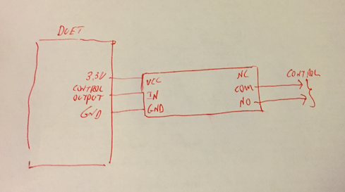
You need to make sure though that the duet 3.3V rail can provide sufficient current to drive that relay (~150ma according to https://www.banggood.com/SONGLE-Mini-3V-DC-Power-Relay-SRD3VDCSLC-PCB-Type-p-926636.html?cur_warehouse=CN ). Others may know if it's ok to do it.
-
The 3v3 regulator is good for 500mA (may need to check temperature ratings), but no idea how much of that the Duet needs for itself.
-
@zapta said in Filament Sensor plus timelapse issue:
I am using a similar one for VCC=24V, but removed the opto coupler and transistor and am driving the coil directly from E2 output ( (left the flyback diode on the board) . https://www.amazon.com/gp/product/B00LW2H5GC
Per the relay datasheet, a 24V version requires only 15mA. Will within the 30mA of which each SAM4E8E pin is capable.
.
Back to the original question, about the 3V version messing up the Filament sensor:
@zapta is correct, if wired like it shows in his post with the hand drawn diagram (and pull the jumper cap on the relay module), that relay module should work fine.
-

I'm only about 90% certain about removing the jumper... the documentation for the relay board is confusing.
