Mesh Calibration Issues (Duet Maestro 1.0, FW 2.02, BLTouch)
-
Howdy,
I've setup my BLTouch with my Maestro, and am able to successfully mesh calibrate. I do not seem to yield the benefits though as often the first layer does not stick if I deviate more than about 100mm away from the center of the bed. I have a 400x400mm build platform and often end up with prints happening either in mid-air or very close to it, with poor adhesion. Mean error on 36 points is -0.126, with max deviation at -0.785/0.463 mm. Is there a particular gcode start command I should add to enable mesh compensation? Some of the guys in the facebook group recommended M420 (which I initially suspected was the 3D printing equivalent to headlight fluid), but it appears that is not a Duet RepRap recognized code.I have change the quantity of mesh leveling points to as many as 400 (though it looks like that crashed my duet so I retried at 100 and that didn't fail) but have had no change in outcome. The BLTouch provides reliable data across multiple mesh data probes.
Any suggestions?
-
Are you executing a G29 S1 before you start printing?
Normally, you'd have this g-code in the bed.g macro and include a G32 command in the slicer's start code settings.Unless you load and activate the saved levelling grid, it won't have any effect.
-
@classicstyle said in Mesh Calibration Issues (Duet Maestro 1.0, FW 2.02, BLTouch):
Mean error on 36 points is -0.126, with max deviation at -0.785/0.463 mm
that seems pretty uneven. can you post a picture of the mesh bed?.
also while printing verify with m122 that the bed compensation is in fact turned on/
-
@grizewald Do I need to run g32 on every print start? I have a mesh stored already, or am I missing the point of G32? Thanks for the tip about G29 S1, the S1 was missing from the command!
-
G32 causes the macro 'bed.g' to be called. There's nothing that requires you to perform a mesh levelling before every print, that's the whole idea with having a command to load a saved mesh.
This is what my bed.g looks like:
; bed.g
; called to perform automatic bed compensation via G32
;
M561 ; clear any bed transforms to start levelling from scratch
G28 ; Home all
G29 S1 ; Load heightmap.csv and activate itThat's it! I create a new levelling mesh every once in a while via a separate macro which warms up the bed and print head to 60C/130C before it probes a grid of 196 points.
My homeall.g macro, which is called when G28 is run, performs a lead screw compensation after the initial homing of X, Y and Z. Once the lead screw compensation is done, it levels Z again, just in case the lead screw compensation changed the Z homing height.
So, my slicer's start code contains a G32, but the macro only loads and activates a previously created mesh rather than creating a new one.
Oh, one last thing. My slicer's start code also warms up the bed and print head to 60C/130C before the G32 is executed. That way, everything is set up to match the conditions under which I created the stored mesh.
After returning from the G32, the start code then sets the bed and print head to the actual printing temperatures before the print itself starts.
-
@grizewald said in Mesh Calibration Issues (Duet Maestro 1.0, FW 2.02, BLTouch):
G32 causes the macro 'bed.g' to be called. There's nothing that requires you to perform a mesh levelling before every print, that's the whole idea with having a command to load a saved mesh.
That's the piece I was mentally missing, thank you! I added the G32 to the start code and have the G29 S1 added to bed.g. Wish me luck! Or don't, in any case I'm going to give it a go shortly!
Thanks again for the generous information @grizewald!
-
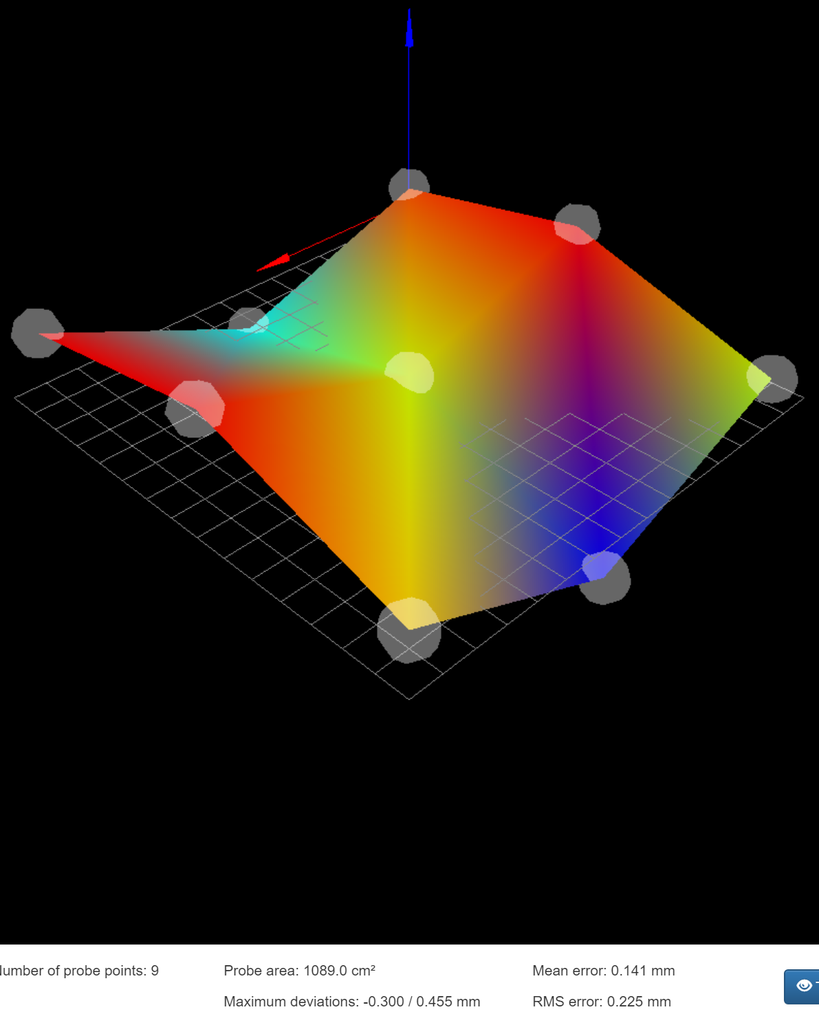
Someone mentioned an image of my calibration. I upped the sample count to 225, and here's what I got:

-
that is not a good base. nearly a mm difference between highest and lowest point.
-
@classicstyle said in Mesh Calibration Issues (Duet Maestro 1.0, FW 2.02, BLTouch):
@grizewald said in Mesh Calibration Issues (Duet Maestro 1.0, FW 2.02, BLTouch):
G32 causes the macro 'bed.g' to be called. There's nothing that requires you to perform a mesh levelling before every print, that's the whole idea with having a command to load a saved mesh.
That's the piece I was mentally missing, thank you! I added the G32 to the start code and have the G29 S1 added to bed.g. Wish me luck! Or don't, in any case I'm going to give it a go shortly!
Thanks again for the generous information @grizewald!
No problem and good luck! Looking at your height map, you'll need it.
My bed is far from flat, but it's nowhere near as bad as yours.
-
Yeah, my build surface is about as smooth as 80 grit sandpaper, which really sucks cause I honestly thought it was very flat.
Has anyone ever tried floating out the surface of an aluminum build plate with some catalyzed resin-like products, then polishing it?
-
Is there a way to verify that mesh compensation is occurring? (besides it just working)?
Also, I'm hoping this is the case, but does compensation interpolate between data points?
-
@classicstyle It does interpolate, which is why a large number of points is a good idea.
To see if mesh compensation is being used, you can:
a. Issue an M122 command at the console after finishing a print. The report that comes back will tell you if mesh compensation is active.
b. Watch the Z steppers as you print. You should see them moving to adjust the Z height on longer moves.Looking at how your bed is below the zero point at three corners, are you sure there is not more you can do mechanically to level the bed? How is the bed attached to your Z axis?
-
@classicstyle said in Mesh Calibration Issues (Duet Maestro 1.0, FW 2.02, BLTouch):
Is there a way to verify that mesh compensation is occurring? (besides it just working)?
Print an STL like this once with mesh disabled and once with it enabled. That will show how effective it is.
-
@grizewald Thanks for the clarity about m122.
I actually have been trying things most of the night and this morning. It seems like every time the wind changes direction, the corners that are above or below zero change. I'm running a dual-z hypercube with 4 12mm guides. I think I'm going to have to figure out a pilot bearing for the top of the cube to make the lead screws more stable cause they do allow the build plate to wobble some.
-
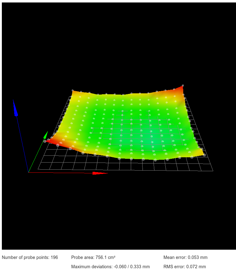
As an example, this is what my levelling mesh looks like:
Not too pretty considering the bed is a 310mm square Anycubic Ultrabase on top of a 329mm square 3mm thick aluminium plate.
I'm considering heating it up as high as my heater will go (around 120C) to see if it might release the stress which seems to have formed after I mounted the glass plate.
I see the Hypercube uses a similar, brain dead, way of mounting the print bed as my V-Core printer. Fixing a plate at four points is just plain dumb. It should be fixed at three points in a triangle only. That way, you can adjust for roll and then adjust for pitch without ruining the first roll adjustment.
I don't know if you're using springs like I see on the Thingiverse page for the Hypercube, but I don't use springs on either of my printers. All I use is nylock nuts to fix the height and keep it fixed. My V-Core's mountings are actually free to move in certain directions to prevent any problems when the bed expands due to heating.
-
@grizewald Thanks for all the insight about 3-point mounting. Something I had definitely never realized. I actually have a Tronxy XY-2 as my first printer and went through the 4-sprung corner madness and said "no thanks, this sucks" to repeating that for my hypercube. I'm solid mounted to a 6-bar 2020 frame. Essentially it's a square frame of 4x2020 extrusion, then two 2020 extrusions are laid across the frame, resting on top of it. It's then solid mounted to the frame, and the bed is solid mounted to those two 2020s via v-nuts. I know it sounds overly complex, but I wanted a lot of adjustability while I dialed in the machine.
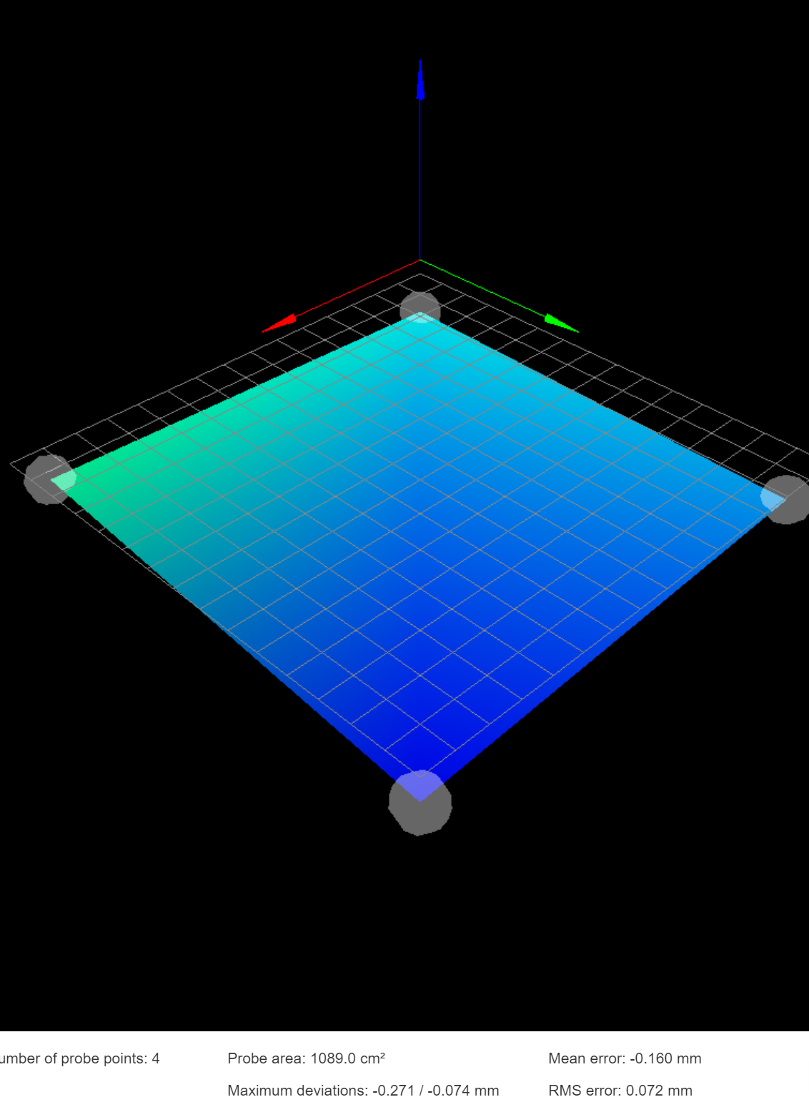
You reminded me that my 90 degree frame-to-2020 mounts are slotted, so I've been trying to dial that in since about 2 messages ago, starting with a simple 9-point grid to rough-in the level, then I'll up the resolution once I have all four corners roughly leveled and as close to 0.00 Z as possible. Getting closer....

For the moment I'm ignoring the middle blue points because I can actually see the swale in aluminum from where I'm sitting.
 I have a mirror on the way to hopefully help this problem long term.
 -
I don't know why it took me so long to realize I should be using my feeler gauges to level the platform.
 But here's the latest. Now that it's mostly flat, I'll worry about raising it to 0-ish tonight. Now time to start increasing resolution.

Edit: ugh, just re-homing the Z should get it to zero-ish. I'm clearly firing on all cylinders today.
-
That looks very nice indeed!
Progress at last eh?
")
-
Indeed.
I did a test print of that stl Phaedrux provided. It failed to print well directly on aluminum, but I did have M122 added to the end of the gcode. Here's the relevant portion:
Bed compensation in use: mesh
Bed probe heights: 0.000 0.000 0.000 0.000 0.000I don't understand the purpose behind the probe heights line - I only have g28 hitting Z probe at one coordinate - the middle of the print bed. Anything to be concerned about?
-
That doesn't look right. All I see if I run M122 is:
Bed compensation in use: mesh, comp offset 0.000
My Z-Probe configuration section looks like this:
; Z-Probe
M574 Z1 S2 ; Z end stop is probe at low value
M558 P8 R0.4 I1 H5 F360 T6000 ; Set Z probe type to inverted, unfiltered piezo and the dive height + speeds
G31 P500 X0 Y0 Z-0.02 ; Set Z probe trigger value, offset and trigger height
M557 X5:285 Y5:275 P14 ; Define mesh gridYour output looks like maybe it's set up to do manual probing. Hopefully someone will recognise what your output means. I'm pretty sure it's nothing to do with homing. I have one homing point which is in the middle of the bed at the same Y point as my two Z axis lead screws are mounted.