Fan: switched GND to switched positive
-
The problem has evolved from converting voltage levels to something else, so I have updated the thread title as well.
The BLDC driver board that I am using has multiple GND pins, and seem internally connected. The main GND pin (next to Vcc) is directly connected to my main PSU's negative terminal. When the 2nd ground and 5V signal is connected to the logic signal side of the board, it basically just adds a permanent 5V source. Normally the Duet would switch the fan output's GND pin, but that has no use in this case.
Any ideas on how to convert a negative switched signal and convert it to positive switched?
-
@Nxt-1
I have an ideas why not hijack the fan mosfet conector and conect it to external mosfet board useing M106 I1 to invert the fan signal or take a look at M950 command there an option to invert siginal
and you can do any thing with the signal bare in mind that the logic will be 3.3 volt you can use opto coupler to convet logic -
Hi,
What is the idea behind using HDD motors?
I use 12 VDC 40x40x20 mm blowers on the normal Duet fan outputs and they work just fine.
Thanks.
Frederick
Printers: a small Utilmaker style, a small CoreXY and a E3D MS/TC setup. Various hotends. Using Duet 3 hardware running 3.4.6
-
@Nxt-1 said in Fan: switched GND to switched positive:
Any ideas on how to convert a negative switched signal and convert it to positive switched?
You'd essentially need to throw a pnp bjt or p-channel mosfet in to do high side switching.
this might give you some insight if you sift out all the irrelevant bits
https://www.baldengineer.com/pwm-3-pin-pc-fan-arduino.html -
@fcwilt said in Fan: switched GND to switched positive:
Hi,
What is the idea behind using HDD motors?
I use 12 VDC 40x40x20 mm blowers on the normal Duet fan outputs and they work just fine.
Thanks.
Frederick
Well first of all, hdd motors and abundant and cheap. Second, I was intrigued by Mark's Rehorst's design, so I decided to play around with it.
@poohzaza said in Fan: switched GND to switched positive:
@Nxt-1
I have an ideas why not hijack the fan mosfet conector and conect it to external mosfet board useing M106 I1 to invert the fan signal or take a look at M950 command there an option to invert siginal
and you can do any thing with the signal bare in mind that the logic will be 3.3 volt you can use opto coupler to convet logicNo need to attach directly to the mosfet connector I would say? I am interested in going the optocoupler way. Drive the coupler with the fan output and switch the 5V path to the driver board, maybe with somthing like a 10k resistor in series to limit current.
-
@bearer said in Fan: switched GND to switched positive:
@Nxt-1 said in Fan: switched GND to switched positive:
Any ideas on how to convert a negative switched signal and convert it to positive switched?
You'd essentially need to throw a pnp bjt or p-channel mosfet in to do high side switching.
this might give you some insight if you sift out all the irrelevant bits
https://www.baldengineer.com/pwm-3-pin-pc-fan-arduino.htmlAny specific reason why a simple optocoupler (see my above post) might not work? I have a bag of optocoupler still laying around so that would be the easy route for me
")
-
@Nxt-1 said in Fan: switched GND to switched positive:
Any specific reason why a simple optocoupler (see my above post) might not work? I have a bag of optocoupler still laying around so that would be the easy route for me
None other than still needing a PNP output from the optocoupler which is less common, and what output current you need.
-
@bearer said in Fan: switched GND to switched positive:
@Nxt-1 said in Fan: switched GND to switched positive:
Any specific reason why a simple optocoupler (see my above post) might not work? I have a bag of optocoupler still laying around so that would be the easy route for me
None other than still needing a PNP output from the optocoupler which is less common, and what output current you need.
Mind sketching a diagram one would wire the transistor (with or without the opto)?
-
either get an optocoupler with an internal PNP instead of the common NPN type, or the link I posted has the plenty of relevant schematics.
-
what is you opto model number
-
@poohzaza said in Fan: switched GND to switched positive:
what is you opto model number
I have a bag of these laying around and just found some old salvaged pnp's. At the moment, my plan is to use the output npn of the opto to drive the pnp transistor as high side switch. I am currently brushing up my bjt knowledge though
-
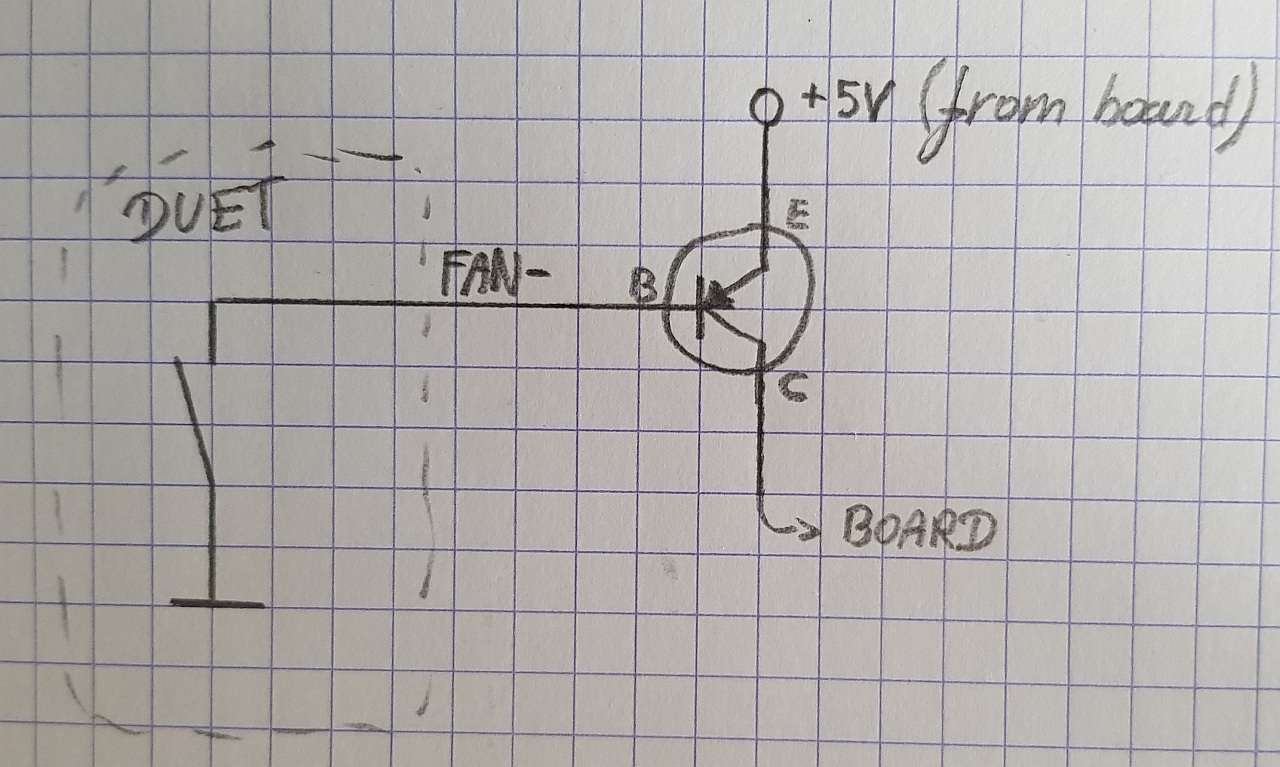
This is what I have in mind atm, I figured the opto coupler does not add a benefit. I also simplified the internal part Duet on the diagram to a simple switch. I decided it is easier to take the 5V output from the driver board instead of a resistive voltage divider from the Duet's V_fan.
I have yet to figure out what current limiting resistors need to be placed in the circuit.
-
this viedo may help you figure out current limiting resistors
https://www.youtube.com/watch?v=WRm2oUw4owE&list=PLAROrg3NQn7cyu01HpOv5BWo217XWBZu0&index=22&t=0s -
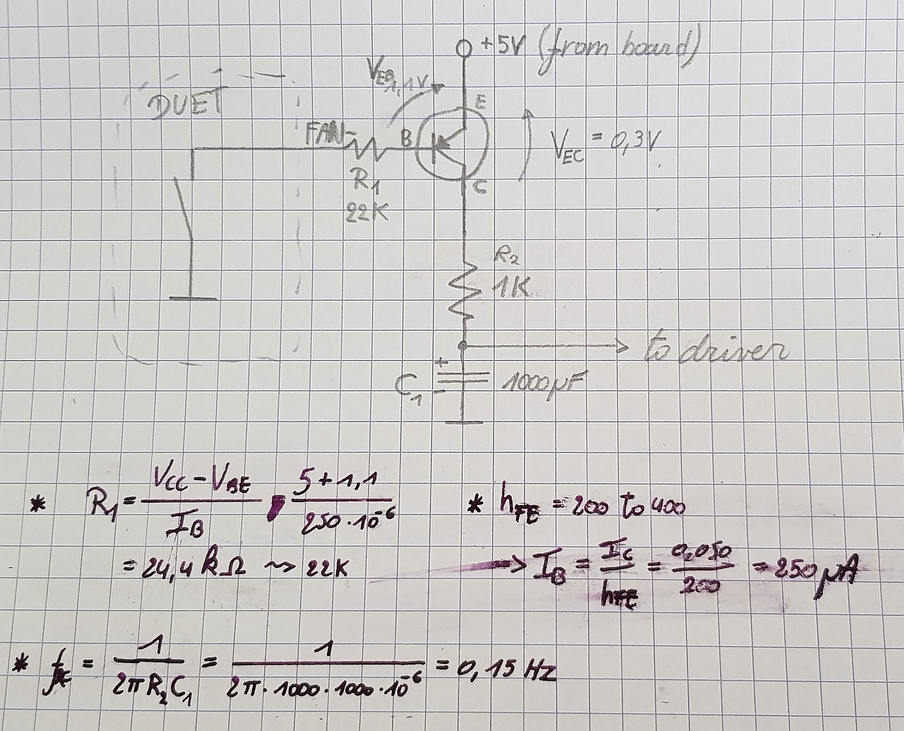
So I assumed a collector current of 50mA, which for the bjt I used, resulted in a ~22K base resistor (if I got it right
). This left me with a working high side switch, pulsing ~0-5V, succes! Sadly hooking the signal to the driver board did not do what I wanted it to. The motor ramped up to max speed and stayed there. My assumption is that the Duet's default 250Hz pwm frequency is not what the driver expects.Therefore I decided to add an aggressive low pass filter to the output and remove the driver board solder bridge (so it expects an analogue voltage 0-5V as speed control). For some unknown reason the output voltage at the cap increased to 5V at the cap charged and stayed there, no matter what pan speed I selected.
Kind of reaching end of my patience for just getting speed control working sadly

-
I should add that I tried changing the Duet fan frequency to 25kHz as well, without success.
-
@Nxt-1 said in Fan: switched GND to switched positive:
Kind of reaching end of my patience for just getting speed control working sadl
you can have a look at
1.did you jumper use external control signal
2.remove low pass fliter and conect pwm siginal then conect jumper for pwm controlcan i have a look at esc datasheet
or cheak that pwm work correctly by conect mutimeter in volt mode you shoud see variable voltage when you adjust the fan siginal
-
The problem is that C1 has nowhere to discharge except through the device that you connect the output to. Here are a few suggestions:
-
In your PNP high side driver circuit, increase R2 to 10K and connect a 1K resistor from the transistor collector to ground. I also recommend adding a 10K resistor between base and emitter of the transistor.
-
Instead of using a PNP transistor etc. use a 74HCT02 gate connected to an expansion board heater output, gated with +3.3V, as we suggest for driving a laser PWM pin. Then connect your RC network to the output of the 74HCT02.
-
Use a PWM to 0-10V VFD converter (readily available on eBay), then a voltage divider to reduce the 0-10V to 0-5V.
-
-
@poohzaza said in Fan: switched GND to switched positive:
@Nxt-1 said in Fan: switched GND to switched positive:
Kind of reaching end of my patience for just getting speed control working sadl
you can have a look at
1.did you jumper use external control signal
2.remove low pass fliter and conect pwm siginal then conect jumper for pwm controlcan i have a look at esc datasheet
or cheak that pwm work correctly by conect mutimeter in volt mode you shoud see variable voltage when you adjust the fan siginal
I did remove the jumper for external control signal. I also tested in pwm mode and tried some pwm frequencies, without success. Sadly with these cheapo controllers, no datasheet is available (at least that I could find).
@dc42 said in Fan: switched GND to switched positive:
The problem is that C1 has nowhere to discharge except through the device that you connect the output to. Here are a few suggestions:
-
In your PNP high side driver circuit, increase R2 to 10K and connect a 1K resistor from the transistor collector to ground. I also recommend adding a 10K resistor between base and emitter of the transistor.
-
Instead of using a PNP transistor etc. use a 74HCT02 gate connected to an expansion board heater output, gated with +3.3V, as we suggest for driving a laser PWM pin. Then connect your RC network to the output of the 74HCT02.
-
Use a PWM to 0-10V VFD converter (readily available on eBay), then a voltage divider to reduce the 0-10V to 0-5V.
I changed the circuit as you suggested and we seem to have a winner. I did lower the LPF capacitance to 10µF, as the rise and fall time was unnecessarily long. I did notice my upper voltage limit is ~3,7V instead of the ideal 5V, but this is not really an issue as 3,7V already corresponds to a very large airflow.
Now I just need to move the components from the breadboard and neatly arrange them on a piece of protoboard.
-