New RepRapFirmware config tool
-
currently the firmware will translate the M667 to the appropriate M669 command.
-
Hi
the arrival of Duet 3 Mainboard is a great news,
have you already planned a date for its integration in the Config Tool ?
thanks -
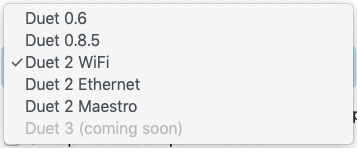
Plans, yes! In Board type, "Duet 3 (coming soon)".
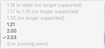
But really it depends on getting RRF 3 configuration working. In Firmware version, "3.xx (coming soon)". No date when this is expected, as far as I'm aware.
Ian
-
Will there be an updated config tool for the Duet 3? If yes will it also work with the Duet 2 as well? With the added flexibility of the Duet 3 it would be really nice if the config too would be able to configure advanced options like adding an axis or two or 5. Not that going into the .g files and configuring the special setups is hard or anything but it would be really nice if a config tool existed for advanced options to handle most of the set up and then jumping into the .g files for final tweaking.
-
Hi
I'm starting to work on the Duet 3, to ease my discovery, is there any one who can share a simple .g file ?? for a standard machine like : cartesian /200x200x250/simple extrudeur/heated bed/z probe. it could help a lot, thanks in advance. -
@steevebecker I can share a simple config.g file for ender5 but duet2 with RRF 3 if that helps
-
@smece hi taht could be good as a first step

i don't how the .g will be different between duet E vs Duet 3.
of course pin out will be different but not sur sure what is the impact on conf ... -
Please note, the nine IO_ connectors don't all have the same capabilities. I have documented them at https://duet3d.dozuki.com/Wiki/Duet_3_Mainboard_6HC_Hardware_Overview#Section_IO. Summary:
- Don't use IO_0 for now
- Don't connect an analog Z probe or a BLTouch to IO_0, IO_1 or IO_2
-
@dc42 thanks for this. I need a lot of I/O so it's good to know.
-
@steevebecker said in New RepRapFirmware config tool:
i don't how the .g will be different between duet E vs Duet 3.
Apart from pin names, the main difference is that there are some default pin assignments for endstops, zprobe and fans in RRF3 for Duet 2, but none in RRF3 for Duet 3. See https://duet3d.dozuki.com/Wiki/RepRapFirmware_3_overview#Section_Default_pin_assignments. So on Duet 2, you may need to use GCode commands to free up some of those pins if you want to use them for something else; whereas on Duet 3 you always need to declare what pins to use for fans, endstops and Z probe.
PS - I am starting to add Duet 3 pin connections to the documentation pages on wiring. For example, I have already added them to the page on connecting Z probes.
-
@steevebecker said in New RepRapFirmware config tool:
@smece hi taht could be good as a first step

i don't how the .g will be different between duet E vs Duet 3.don't know anything about duet3 so can't help there, just recently tried the duet2 myself (was sitting in a drawer for year+, I'm mostly smoothieware user and was delaying duet3d testing as I dislike the structure of RRF source code and I love to tinker with the code, now I'm at a place where with 2 kids time is so darn scarce that I just need something that works and I don't care to tinker if I don't have to so for those type of projects duet looks like ideal solution hence me digging in) and I started out with RRF3 figuring, if I'm diving into it, better start with latest, especially if a lot changed so RRF2 knowledge will have to be scrapped anyhow
 ... so hopefully this will help you and not lead you astray
- XYZ moves, homes..
- BED, E0, E1 heats
- E0, E1 extrudes (have not calibrated yet steps but I'm mounting dual flex3drive here so exact steps_per_mm values would not be useful for you anyhow)
- bltouch works in terms of - deploy, retract, have not yet tested actual probing and mesh compensation since I just designed the holder for flex3drive + bltouch for ender5 so hopefully I'll be testing it today (just printed, hopefully it's properly designed
 )
) - have not yet tried actually printing!!!
config.g
deployprobe.g
retractprobe.g
homey.g
homex.g
homeall.g
homez.gsuper important note to be aware of - I never used duet before, I just mounted it recently on this ender5 and started with RRF3 so while this "moves" and "heats" and "extrudes" I have not yet started printing with it (still working out mount for flex3 drive and waiting on some connectors for hexagon hotends) so make sure these do not lead you astray instead of helping you out!!!!
-
@smece Thanks for you time and file, i ll digg in

-
you are welcome, I'm sure there's much to be done there so post progress here
 so we can both learn from it
-
Hi Duet Forum.
I have spent 2 days on RRF3 and Duet 3. I was my first hours on it ... It's a pleasure, i like this board. I'm moving from another board + Marlin to this one.
Of course it was not so obvious, but with the Documentations (already great) and the forum postsss, I made good progress.
3 Axis+ Endstops / 2 extruders + Sensors + Fans / BED / Heated Chamber / ... everything works. few things are not working yet, i'll write other posts about them.I share here my config.g, hopes it could help :
; Configuration file for Duet 3 (firmware version ?.0??) ; executed by the firmware on start-up ; oct 2019 : X/Y/Z E1/E2 BED/CHAMBER OK - BL (not ready) SERVO (not ready) ; DUET 3 6HC + 1 extension board 3HC (address 1.) ; ; General preferences G90 ; send absolute coordinates... M83 ; ...but relative extruder moves M550 P"QualupQ3" ; set printer name Qualup Q3 http://www.spiderbot.eu/qu3-high-temperature/?lang=en ; Network M552 P0.0.0.0 S1 ; enable network and acquire dynamic address via DHCP M553 P0.0.0.0 ; netmask M554 P0.0.0.0 ; gateway M586 P0 S1 ; enable HTTP M586 P1 S0 ; disable FTP M586 P2 S0 ; disable Telnet ; Drives ;M569 P0 S1 ; physical drive 0 goes forwards / driver 0 unable on this board M569 P1 S1 ; X physical drive 1 goes forwards M569 P2 S1 ; Y physical drive 2 goes backwards M569 P3 S1 ; Z0 physical drive 3 goes forwards M569 P4 S1 ; Z1 physical drive 4 goes forwards M569 P1.0 S1 ; E0 physical drive 1.0 on expansion board goes forwards M569 P1.1 S1 ; E1 physical drive 1.1 on expansion board goes forwards M584 X1 Y2 Z3 E1.0:1.1 ; set drive mapping 1 stepper on X, Y and 2 Steppers (Z3 instead of Z3:4 because Moteur Z1 not plug on Driver 4 at this time) on Z and Extruder M350 X16 Y16 Z16 E16:16 I1 ; configure microstepping with interpolation M92 X80.00 Y80.00 Z400.00 E4074.37:4074.37 ; set steps per mm M566 X900 Y900 Z120 E150:150 ; set maximum instantaneous speed changes (mm/min) M203 X6000 Y6000 Z1200 E1200:1200 ; set maximum speeds (mm/min) M201 X500 Y500 Z100 E250:250 ; set accelerations (mm/s^2) M906 X1000 Y1000 Z1200 E800:800 I30 ; set motor currents (mA) and motor idle factor in per cent M84 S30 ; Set idle timeout ; Axis Limits M208 X0 Y0 Z0 S1 ; set axis minima M208 X300 Y250 Z300 S0 ; set axis maxima ; Endstops M574 X1 S1 P"io6.in" ; X min active high endstop switch / pin io3.in doesnt work use 6 instead M574 Y1 S1 P"io4.in" ; Y min active high endstop switch M574 Z1 S1 P"io5.in" ; Z min active high endstop switch ;Servo ;not working for the moment ;M950 S0 C"io7.out" ;not working for the moment ;M280 P0 S1500 I1 ;not working for the moment ; Z-Probe ;not working for the moment ;M558 P9 C"zprobe.in" H5 F120 T3000 ; FW v3 BLTouch connected to Z probe IN pin ;M950 S0 C"exp.heater3" ; FW v3 create servo/gpio 0 on heater 3 pin on expansion connector ;G31 P500 X10 Y20 Z2.5 ; set Z probe trigger value, offset and trigger height ;M557 X15:6 Y15:195 S20 ; define mesh grid ; TEMPERATURE Sensors M308 S0 P"temp0" Y"thermistor" T100000 B3950 ; BED temperature sensor M308 S1 P"1.temp1" Y"thermistor" T4606017 B5848 C0 R4700 H0 L0 ; head 0 temperature sensor on expansion board ==> DYZE 500 M308 S2 P"1.temp2" Y"thermistor" T4606017 B5848 C0 R4700 H0 L0 ; head 1 temperature sensor on expansion board ==> DYZE 500 M308 S3 P"temp1" Y"thermistor" T100000 B3950 ; Chamber temperature sensor M308 S4 P"temp2" Y"thermistor" T100000 B3950 ; CAMERA IR temperature sensor ; Heaters M950 H0 C"out0" T0 Q100 ; BED heater 3 uses the out0 pin, sensor 0 M950 H1 C"1.out1" T1 ; HEAD heater 1 uses the out1 pin on expansion board and sensor 1 ;M950 H1 C"1.out1" T1 A584.4 C256.6 D6.4 S0.50 ; HEAD heater 1 uses the out1 pin on expansion board and sensor 1 ==> DYZE PID Cartbridge M950 H2 C"1.out2" T2 ; HEAD heater 2 uses the out2 pin on expansion board and sensor 2 M950 H3 C"out1" T3 ; CHAMBER heater 3 uses the out1 pin and sensor 3 M950 H4 C"out2" T4 ; IR Camera heater 4 uses the out2 pin and sensor 4 ; Maximum Temperatures Currently (September 2019), RRF3 does not support M143. ;M143 H0 S380 C0 ; BED max Temp 300°C ;M143 H1 S500 C0 ; Extruder 1 max Temp 500°C ;M143 H2 S500 C0 ; Extruder 2 max Temp 500°C ;M143 H3 S380 C0 ; Chamber max Temp 300°C ; Minimum Temperatures ;M302 P1 S240 R240 ; minimun extruder 1 Temperature 240°C extrusion and retract ;M302 P2 S240 R240 ; minimun extruder 2 Temperature 240°C extrusion and retract ; Fans M950 F0 C"1.out7" ; Extruder 1 fan 0 !F1 don t work ... ??? on pin out 7 pwm on expansion board M950 F2 C"1.out8" ; Extruder 1 fan 2 on pin out 8 pwm on expansion board M950 F3 C"out7" ; Chamber fan 3 on pin out 7 pwm M950 F4 C"out8" ; IR Camera fan 4 on pin out 8 pwm ; Tools M563 P1 D0 H1 F0 S"Extruder 1" ; define tool 1 - F1 don t work... ??? G10 P1 X0 Y0 Z0 ; set tool 1 axis offsets G10 P1 R0 S0 ; set initial tool 1 active and standby temperatures to 0C M563 P2 D1 H2 F2 S"Extruder 2" ; define tool 2 G10 P2 X0 Y0 Z0 ; set tool 2 axis offsets G10 P2 R0 S0 ; set initial tool 2 active and standby temperatures to 0C M563 P3 H3 F3 S"Chamber" ; define tool chamber G10 P3 R0 S0 ; set initial tool 3 active and standby temperatures to 0C M563 P4 H4 F4 S"Camera IR" ; define tool IR Camera G10 P4 R0 S0 ; set initial tool 4 active and standby temperatures to 0C ; Custom settings are not defined -
Hey !
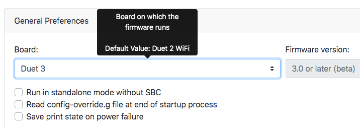
I missed the announcement ?? Duet 3 available on ==> RRF Cofiguration tool here : RRF Config ToolThanks for that !!!!
-
@steevebecker give it a go, feedback requested

-
@T3P3Tony first test works well:
My conf:
On 6HC:- X-Y-Z steppers
- endstop X-Y-Z NC/low end
- Bed heater + T°
- Chamber heater + Fan + T°
- Filament compartiment T°
- Electronic compartiment T°+ Fan
then on 3HC - 2 Extruders - 2 Fans- 2 Thermocouples
- 1 Servo
- 2 filaments presence
- IR Camera T°+ Fan
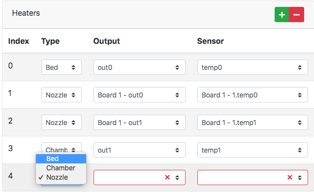
Just a Question How to add a T° sensor with out a heater ? Bed/Chamber/Nozzle Heaters are possible but can I add a sensor alone on a I/O with the RRFCT ? same for a Servo

-
@steevebecker said in New RepRapFirmware config tool:
Just a Question How to add a T° sensor with out a heater ? Bed/Chamber/Nozzle Heaters are possible but can I add a sensor alone on a I/O with the RRFCT ? same for a Servo
AFAIK you need to add these manually to your config.g as the config tool does not set them up for you.
See https://duet3d.dozuki.com/Wiki/Gcode#Section_M308_Set_or_report_sensor_parameters
Uf you give the sensor a name it should show up in the "extras" tab in DWC
-
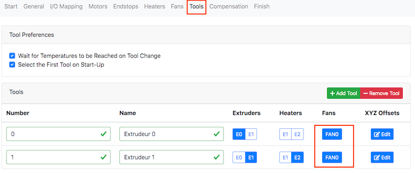
the tool tabs does not allow to select anything else that E0 for extruder, heater and fan
-
@Veti I have partially the same problem
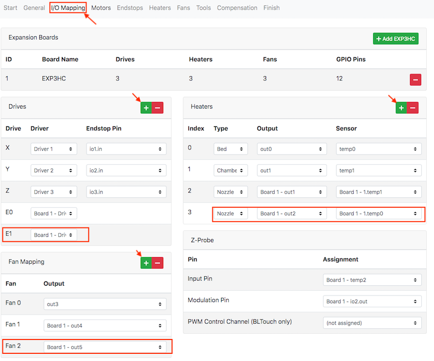
in the I/O Mapping Tab, I have added : +1 Driver for the second extruder, +1 Heater, +1 Fan
pin out everything
but then in the Tool Tab, tools there is only FAN0 available for any tool.
I/O TAB:
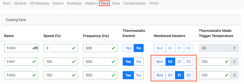
Fan TAB seems ok:
But then in the Tool TAB
