• Tags
  • Documentation
  • Order
  • Register
  • Login
Duet3D Logo Duet3D
  • Tags
  • Documentation
  • Order
  • Register
  • Login

Help diagnosing my delta bed level woes

Scheduled Pinned Locked Moved
General Discussion
6
17
631
Loading More Posts
  • Oldest to Newest
  • Newest to Oldest
  • Most Votes
Reply
  • Reply as topic
Log in to reply
This topic has been deleted. Only users with topic management privileges can see it.
  • undefined
    timmo
    last edited by 22 Nov 2019, 21:42

    Good evening folks, I am having a bit if trouble with a new build. Any help is appreciated.

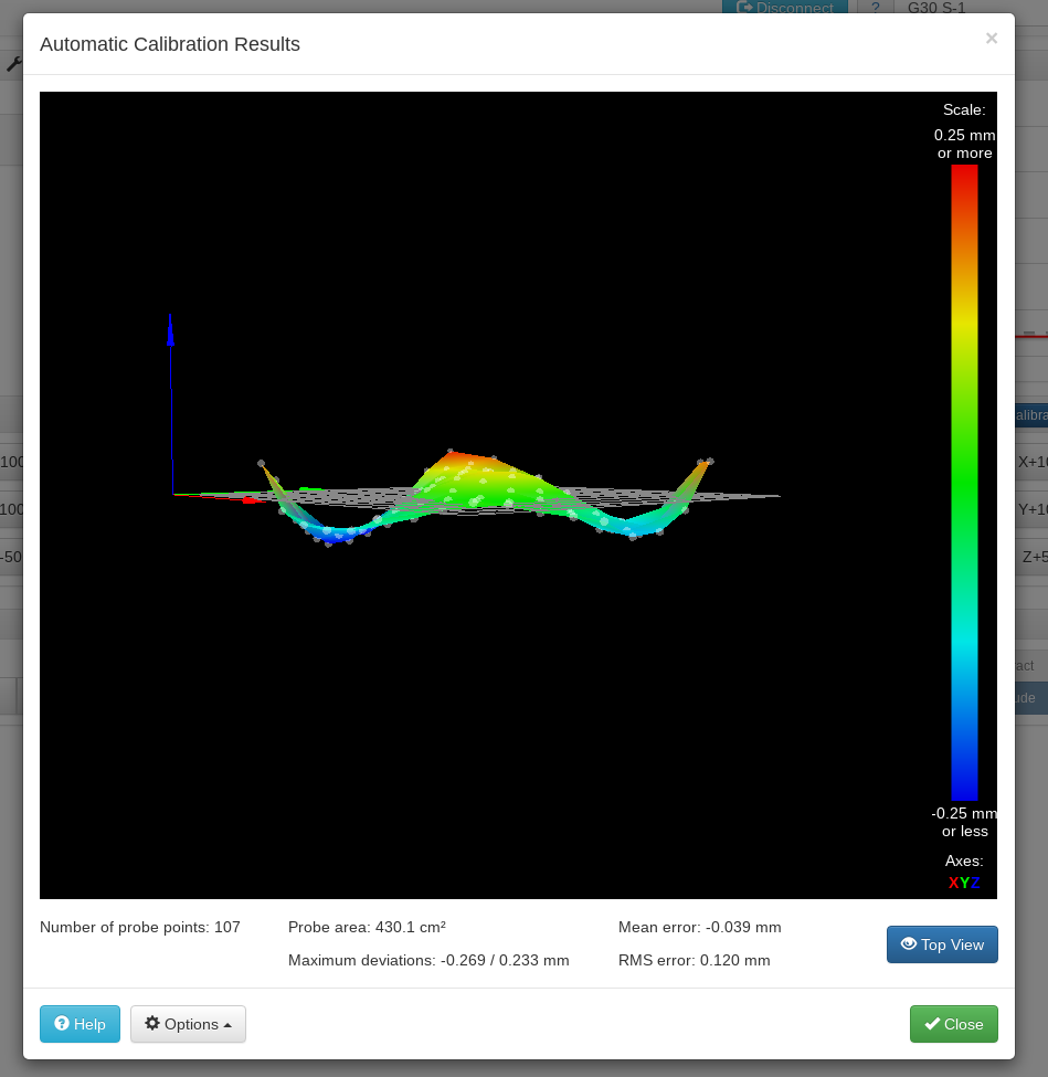
    I am fairly satisfied with the build mechanically... What might be leading to the sinusoidal pattern here:

    b665a24f-b8d4-4296-9365-cccfd38c25f5-image.png

    bcce211e-ecac-4287-8dce-4fd2c76aec8b-image.png

    Thanks in advance,
    Tim

    1 Reply Last reply Reply Quote 0
    • undefined
      Danal
      last edited by Danal 23 Nov 2019, 06:36

      Is the nozzle the probe?

      I'd look for something causing effector tilt. When probing this can cause similar patterns.

      Please post your bed.g

      With mesh turned off, what is the console log result of a G32? Something like:

      G32
      Calibrated 8 factors using 16 points, deviation before 0.388 after 0.074

      Delta / Kossel printer fanatic

      1 Reply Last reply Reply Quote 0
      • undefined
        Danal
        last edited by 23 Nov 2019, 06:42

        By the way, nice looking build!

        Delta / Kossel printer fanatic

        1 Reply Last reply Reply Quote 1
        • undefined
          dc42 administrators
          last edited by 23 Nov 2019, 09:35

          @timmo, please provide another view of the height map from a slightly elevated position, so that we can better understand the overall pattern.

          Have you run auto delta calibration, and if so how many probe points and factors did you use?

          Duet WiFi hardware designer and firmware engineer
          Please do not ask me for Duet support via PM or email, use the forum
          http://www.escher3d.com, https://miscsolutions.wordpress.com

          1 Reply Last reply Reply Quote 0
          • undefined
            T3P3Tony administrators
            last edited by 23 Nov 2019, 14:44

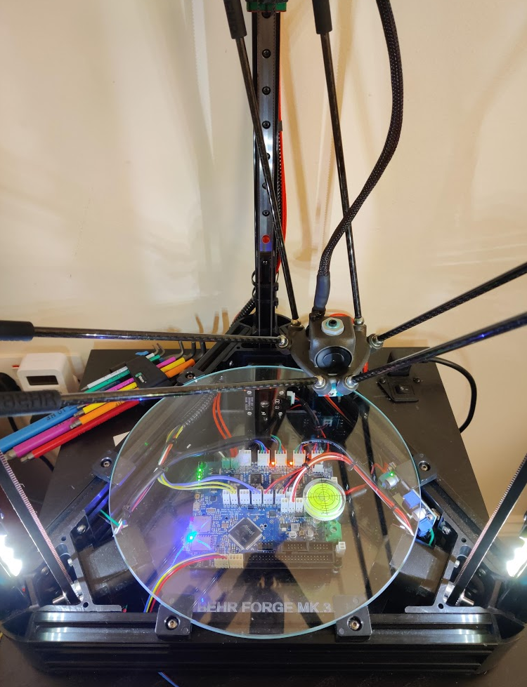
            hi @timmo is the BEHR forge your own design btw?

            www.duet3d.com

            undefined 1 Reply Last reply 24 Nov 2019, 17:57 Reply Quote 0
            • undefined
              timmo
              last edited by 24 Nov 2019, 17:53

              @Danal @dc42

              • The probe is a micro switch that mounts below the nozzle (borrowed from an Anycubic branded kossel).
              • Here is my bed.g file.
              • I didn't pay attention to these log messages on Friday, why might the probe not be able to reach the coordinates (100, -60) and its mirror? Bed size is 240mm in diameter.

              Warning: Skipping grid point (100.0, -60.0) because Z probe cannot reach it
              Warning: Skipping grid point (60.0, -100.0) because Z probe cannot reach it
              107 points probed, min error -0.331, max error 0.273, mean -0.112, deviation 0.124
              Height map saved to file heightmap.csv
              Warning: Skipping grid point (100.0, -60.0) because Z probe cannot reach it
              Warning: Skipping grid point (60.0, -100.0) because Z probe cannot reach it
              G32
              Calibrated 8 factors using 17 points, deviation before 0.142 after 0.128

              I am unable to upload any images at the moment, I am getting the error message something went wrong while parsing server response. 😐

              • The top view of the height map does look irregular - most obviously two probe points are missing in one corner of the octagon. Sides of the octagon in the X and Y planes are bowed inwards slightly. I will upload an images possible.

              Thanks again!

              1 Reply Last reply Reply Quote 0
              • undefined
                timmo @T3P3Tony
                last edited by timmo 24 Nov 2019, 17:57

                Hello @T3P3Tony, yes, I have plastered BEHR over most of the parts I made for this. My second name is Behrman - its an ego problem I think

                1 Reply Last reply Reply Quote 0
                • undefined
                  Veti
                  last edited by 24 Nov 2019, 18:03

                  please post your config and overwrite.

                  undefined 1 Reply Last reply 24 Nov 2019, 20:39 Reply Quote 0
                  • undefined
                    Veti
                    last edited by 24 Nov 2019, 18:10

                    also this is a good read.
                    http://boim.com/DeltaUtil/CalDoc/Calibration.html

                    1 Reply Last reply Reply Quote 1
                    • undefined
                      timmo @Veti
                      last edited by timmo 24 Nov 2019, 20:39

                      Good evening @Veti, config-override.g config.g

                      That is a good read, thanks for sharing that!!

                      1 Reply Last reply Reply Quote 0
                      • undefined
                        Danal
                        last edited by Danal 25 Nov 2019, 02:17

                        why might the probe not be able to reach the coordinates (100, -60) and its mirror

                        From your config.g, printable radius is 117.
                        M665 R135 L290 B117 H300

                        Or your config override:
                        M665 L290.000:290.000:290.000 R133.311 H265.868 B117.0 X-1.335 Y-0.543 Z0.000

                        A 100x60 unit rectangle just touches the limit of a 117 unit circle. To Scale:

                        alt text

                        Delta / Kossel printer fanatic

                        1 Reply Last reply Reply Quote 0
                        • undefined
                          Dougal1957
                          last edited by Dougal1957 25 Nov 2019, 13:57

                          I would generate a new bed.G file using 110-115 Radius and try again you can use the config tool for this or use the one on Eschers web page Bed file generator use 6 factor and as many points as you like I would use 10 peripheral and 6 intermediate points (you can edit the output file to change the S6 at the end to S8).

                          ; bed.g file for RepRapFirmware, generated by Escher3D calculator
                          ; 16 points, 6 factors, probing radius: 115, probe offset (0, 0)
                          G30 P0 X0.00 Y115.00 Z-99999 H0
                          G30 P1 X73.92 Y88.10 Z-99999 H0
                          G30 P2 X113.25 Y19.97 Z-99999 H0
                          G30 P3 X99.59 Y-57.50 Z-99999 H0
                          G30 P4 X39.33 Y-108.06 Z-99999 H0
                          G30 P5 X-39.33 Y-108.06 Z-99999 H0
                          G30 P6 X-99.59 Y-57.50 Z-99999 H0
                          G30 P7 X-113.25 Y19.97 Z-99999 H0
                          G30 P8 X-73.92 Y88.10 Z-99999 H0
                          G30 P9 X0.00 Y57.50 Z-99999 H0
                          G30 P10 X49.80 Y28.75 Z-99999 H0
                          G30 P11 X49.80 Y-28.75 Z-99999 H0
                          G30 P12 X0.00 Y-57.50 Z-99999 H0
                          G30 P13 X-49.80 Y-28.75 Z-99999 H0
                          G30 P14 X-49.80 Y28.75 Z-99999 H0
                          G30 P15 X0 Y0 Z-99999 S6
                          1 Reply Last reply Reply Quote 0
                          • undefined
                            Veti
                            last edited by 25 Nov 2019, 20:40

                            you have a M665 H265.8 command after the M501 overwriting your overwrite.

                            M305 P1 T100000 B4138 R4700 ; Set thermistor + ADC parameters for heater 1

                            that B4138 is the default and almost certainly wrong for your thermistor.

                            G31 P100 X-0.8 Y0.9 Z14.23 ; Set Z probe trigger value, offset and trigger height - Probe V2

                            thats a strange offset. is that because of the changed effector?

                            btw i changed the probe on my Kossel Linear plus with this one and i am much happier.
                            https://de.aliexpress.com/item/32841075715.html?spm=a2g0o.productlist.0.0.3def725epnbpTZ&algo_pvid=e1290575-fb8d-4525-94eb-6b75cf2be7fa&algo_expid=e1290575-fb8d-4525-94eb-6b75cf2be7fa-0&btsid=567f548b-df48-4a1a-8768-880feb9f1e62&ws_ab_test=searchweb0_0,searchweb201602_3,searchweb201603_55

                            1 Reply Last reply Reply Quote 0
                            • undefined
                              timmo
                              last edited by timmo 26 Nov 2019, 20:49

                              I have been unable to upload screenshots of the height map to the forum so I have put uploaded into a google doc here:
                              https://docs.google.com/document/d/12lG_zHno2UNuHDC7RJ9nZtWuhsHGS9znnXJKTbSSxZU/edit?usp=sharing

                              @Danal and @Dougal1957 This is much more clear to me now, I have edited the bed.g file and the printer is hitting all the probe points now. Thank you

                              @Veti I liked the idea of the Anycubic probe when I was modelling the effector, in hindsight I would have gone with a Duet strain gauge effector. I have ordered the probe you linked, will give it a go. I have not payed much attention to the heater control yet - I'm panning to start reading about this, thank you too.

                              Which software parameters might be leading to the bed level pattern?

                              After reading the 'Calibration of Delta 3D Printers' that Veti posted I'm going to check for mechanical errors. There's not much in the way of backlash and the rods all within 10 microns of 290mm. I will check all the magnets are pressed into printed parts fully.

                              undefined 1 Reply Last reply 27 Nov 2019, 19:59 Reply Quote 0
                              • undefined
                                timmo @timmo
                                last edited by 27 Nov 2019, 19:59

                                Edit: my rods are 285mm from the ball ends center to center

                                1 Reply Last reply Reply Quote 0
                                • undefined
                                  dc42 administrators
                                  last edited by 27 Nov 2019, 21:36

                                  Are the joints magnetic, or something other type? The sharp curl up at the edges suggests to me that the joints are running out of movement.

                                  Duet WiFi hardware designer and firmware engineer
                                  Please do not ask me for Duet support via PM or email, use the forum
                                  http://www.escher3d.com, https://miscsolutions.wordpress.com

                                  undefined 1 Reply Last reply 28 Nov 2019, 18:42 Reply Quote 0
                                  • undefined
                                    timmo @dc42
                                    last edited by timmo 28 Nov 2019, 18:42

                                    @dc42 Magnetic, threaded steel balls sitting in countersunk disk magnets. There is ample clearance around the ball
                                    joints for movement.

                                    1 Reply Last reply Reply Quote 0
                                    6 out of 17
                                    • First post
                                      6/17
                                      Last post
                                    Unless otherwise noted, all forum content is licensed under CC-BY-SA