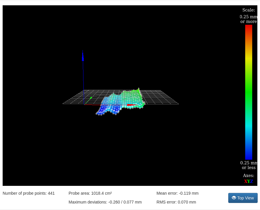
What could cause this heightmap pattern
-
@4lathe left side
-
@jens55 Let me clarify what I meant with points 3 and 4:
Visual check: I meant you can check visually with a precision tool whether it is really your print bed which has this form or the gantry or other error A hairlineal allows to see unevenness, but if you don't have one you could use something other very even. The goal is to decide where the problem can be.
Mechanical reason: I mean that your printer has two actuators to move Z, so there is a possibility that the two hinder each other moving. One possibility is that they get stuck at the sides. You can test it by temporarily more mass load on the hotend, so effects like backlash or angled axis will show in the meshmap (becoming better or worse). The mass should not be so high that the steppers don't move any more but high enough (maybe 1 kg). More differences => stuck of the movement, less differences => backlash effect.
-
@jens55 One thought to the screws: if they are steel screws, e-module is 210 for steel, aluminium is 70 and glass between 40 and 90, so a thermal expansion will bend the aluminium and glass, not the screws. So I wouldn't completely rule it out as possible reason.
Thermal expansion of Aluminium is about 1.5 mm for 100 degree difference for 500 mm. I was surprised to calculate how much a plate bends: the calculator https://www.arndt-bruenner.de/mathe/scripts/kreissehnen.htm tells me, if 500 mm is compressed to 501 mm (s = 500, b = 501) and the plate bends because the screws fix it, it bends by 13 mm height (value a)! (incredible and counterintuitive). So even if it only bends the plate a bit, this may be enough.
Bending of glass without thermal effect could be because of former expansion bending and hysteresis effect, not being flat after cooling down. -
The screws are 4mm steel but the glass plate is of course not 'fixed' as such but held on with spring clips in the corners. I never did bother to calculate the rate of expansion for aluminum. Although it is higher than I would have guessed at 1.5 mm, I am not terribly surprised. That is 0.75mm per screw so yes, I can see a bit of bending happening. But again, I would expect a somewhat even bending rather than a linear bending that I see.
13mm of bending ??? Not a chance. The screws will move first. Some bending - possibly ... but again, the glass bed is somewhat isolated from the aluminum and again the linear pattern of distortion seems counter-intuitive. STill, I suppose it is possible.
I wonder what the map would look like if I removed the corner clips. The probing happens slow enough so the plate doesn't move by itself without he clips and it will be an interesting thing to find out. -
How does it look with nothing heated?
-
@4lathe , very similar to the heated version. Certainly the overall shape (without comparing individual data points) of the map looks the same.
-
Well this was very interesting ... running the mesh bed probe with no spring clips at the four corners of the glass plate produced a completely different result. Yes, there were some similarities but overall the picture looked quite different.
I am now running another mesh probing but with the glass plate turned 90 degrees around it's vertical axis to see if the pattern follows the rotation. -
Ok, repeated the height map with the glass turned 90 degrees and the pattern features of the map did not rotate with the glass. I am left assuming that maybe there is a slight abnormality in the gantry producing this pattern.
Of more importance to all of this is the tremendous amount of change in the height pattern that is introduced by simple bed clamps. These aren't even heavy bulldog clamps but light picture frame clamps! This is something completely unexpected and I must admit to dealing rather haphazardly with clamps in the past in general. I have been moving them here or there without reason. Sometimes I added a bulldog clamp - random stuff really.
What this test shows is that leaving absolutely EVERYTHING identical between a calibration run and any subsequent prints is CRITICAL !!! Even the lowly glass plate to bed plate can throw the whole works off.This has been most enlightening indeed !
-
I'd be inclined to do some light disassembly of the Y axis and see how it slides.
-
One of the reasons I went to indepandant z motors was that the gantry would slide down way too easy when there was no holding current so I doubt there is a stiff spot. In the great picture of things, the aberrations are immaterial but it was important to me to know why I see them. My curiosity has been satisfied and I will leave 'good enough' alone.
It has been a tremendous learning experience no matter what! -
Are you probing with bed heat on? If so, do you have the B1 parameter in your M558 command, to turn the heaters off during probing? Some bed heaters generate enough magnetic field to affect a BLTouch.
Duet WiFi hardware designer and firmware engineer
Please do not ask me for Duet support via PM or email, use the forum
http://www.escher3d.com, https://miscsolutions.wordpress.com -
If you are going to use clamps you should only use them in 3 places. 3 points determine a plane and 4 clamps over constrains a plane.
Is there anything in your wire loom that is binding the carriage? -
@dc42 , B1 is turned on
-
@4lathe , I am aware of the 3 point thing but the bed is supported at three points so I decided to keep that going to the glass plate.
No on the binding wire loom. -
Where you have the ridges and valleys in the Y direction towards the right hand end of that height map, I would be interested to see what it looks like if you probe that part of the bed with a smaller X spacing.
-
I just started a 9 hr print but I will run a mesh probe tomorrow as per request.
-
Interesting pattern ....! Just not sure what it tells me.
-
Interesting indeed! Did you try rotating the bed 90 degrees?
-
It is a CR10S-5 .... whoa .... the original post vanished
")
Anyway, aluminum v rails, aluminum bed, glass plate on bed.
Ha .. a new question appears
Yes, tried rotating, no difference. -
I still think your Z axis is stuck due to different movements of left and right. I would put 0.5 kg additional weight on the hotend temporarily and measure again. This will show you the problem, because it will make it worse or better.