3 x Z-Axis - Idea vs Engineering reality
-
Anyone know of a decent UK supplier for the ball screws used in this vid ...
The printer in the vid uses a Duet 2.
The text calls them DIN 71803 ball head screws in 8mm
I found this because the design I implemented doesn't work - any attempt to adjust bed level using leadscrew directly mounted to the bed just causes binding in the leadscrew nuts.
-
@Garfield According to a later comment, the ball screws are standard SFU1204, Chinese HI WIN copies for rails.
Rene Bormann
2 months ago
Moin Stefan, are these 1204 BallScrews?Stefan Wenn
2 months ago
Yes, exactly SFU1204Rene Bormann
2 months ago
@Stefan If thanks - I just ordered it. Hope to be able to print your parts when they're done.
Have now watched your video at least 30 times - love the engine noise when moving.- Are they OK? https://de.aliexpress.com/item/32885212327.html?spm=a2g0s.9042311.0.0.27424c4deKaN7o
- What motors are you using?
Stefan Wenn
2 months ago
@Rene Bormann- yes I have such spindles too. But I've had it for a few years now, there is no link to it anymore.
- I still had three of the same nema17 engines lying around. I can't tell you more than that the 1.8 ° step angle. But I don't think they're that critical either
Rene Bormann
2 months ago
@Stefan Wenn Merci! Last question, are these "simple China Rails" or HIWIN?Stefan Wenn
2 months ago
@Rene Bormann unfortunately only China rails.The DIN 71803 are the ball studs that the bed is mounted on (see below). Not sure how the dowel pins fit in.
Sebastien Lacasse
5 months ago
What kind of ball joint did you use to hold the bed platform? And where did you get them ?
Relly nice design btwStefan Wenn
5 months ago
Hey Sebastian. I used DIN 71803 ball head screws in 8mm diameter and I got them from ebay. The counterpart are two 25x5mm dowel pins which I got from a local store.Ian
-
I should clarify that the issue for me isn't the leadscrews that I have - the problem is how they're connected to the bed. In the design that I based my printer on the bed mounts are rigid. The only free movement in the Z axis is whatever free play is in the leadscrew nuts - practically zero - so if the steppers are out of synch it binds like crazy. It is the Maxwell joint between the bed and the frame that is really of interest
Currently deep in thought about changing out my leadscrews for ball screws but I'll be sticking to 8mm.
I'm going to need to rework my bed mounting so I'm definitely headed down this support route.
Need to figure the spring part and how to accomodate within the frame constraints.
I found the ballscrews in Germany easy enough but nothing here strangely enough.
I also considered using something like this instead of the Maxwell joint and springs
or maybe the ball joint and springs.
-
@Garfield the maxwell linkages allow for the spacing between the mounts to vary as the joints move. so using a ball socket joint will not work well
-
Appreciate that pointer - been a while since I did any trig ... I was rapidly headed down the rose joint route because I forgot the hypotenuse rules ... reminder assimilated .... time to find some rollers / dowels / springs
-
@Garfield I used a kinematic mount in my printer and have since seen similar mounts done on lead screws. One bed support is a ball head screw sitting in a chamfered hole in the bed plate, another is a ball head screw sitting in a chamfered slot, and the third point just supports the flat underside of the bed.
I my printer I use two belts to lift a T shaped bed support structure, but if you're using 3 lead screws, you could probably do away with T shaped bed support and just lift the bed on the ball head screws.
The kinematic mount allows the bed to tilt with the leveling screws (in your case, with the movement of the lead screws), and to expand when heated without pushing the screws sideways. In my printer the bed does not have to be releveled unless I take the Z axis apart.
This is the bed support- you could just mount the leveling screws on the Z axis bearing blocks. The springs hold the bed plate down on the screws:

Here's the underside of the bed plate- if you look closely, the left ear has a hole and the right ear a short slot in which the the ball head screws sit.

If you don't have access to a mill, the slot can simply be cut through the edge of the plate with a saw. The slot only needs to be a couple mm long.
It looks like this when it's assembled:
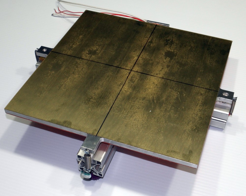
Note: the photo of the plate above is from another printer that I set up with kinematic mount- it was the clearest photo I had of the bed.
More details here: https://drmrehorst.blogspot.com/2017/07/ultra-megamax-dominator-3d-printer-bed.html
-
@Garfield if it would help I did a three axis that allows for accommodating the dimensional changes you have to accommodate, with links.
-
It's clear my design that I thought complete is now nowhere near - this will solve so many of the issues that I have fought with on the Prusa that relies almost entirely on software to correct deficiencies in levelling - the ability to manually level is very limited.
This kind of levelling done correctly has to be the best there is - you only need mesh bed levelling to deal with surface imperfections based on what I'm seeing.
I'm currently playing around in Fusion to see how I can make this work within the frame confines that I have (pretty much 500mm square) without compromising my build area.
@Nuramori - what did you CAD yours up in ? - stl are of limited value in a package like Fusion - I'd be interested to see how you have achieved the flexibility and whether I could make this work on my frame. What is the reasoning behind the one, two and three point mounts ? Why aren't they all two or three point ?
-
@Garfield I don't use mesh bed leveling either, just a flat cast aluminum bed plate, 300x300x8 mm, with a 0.7mm layer of PEI.
If you drive 3 screws with 3 motors you have to use some active leveling because you used 3 motors to drive 3 screws. It's a self-fulfilling prophecy. If you turn the three screws with one motor they won't get out of sync and the bed won't tilt. It doesn't make for exciting youtube videos, but it just works and works. You have to decide which you prefer.
I routinely drag my printer up the basement stairs, load it into my car on its back, drive it across town, take it out and stand it up and start printing without making any adjustments. Then I haul it back home, bounce it down the basement stairs, turn it on and start printing.
-
I'm hoping this can be a 'rarely used' feature.
The intent - drive the bed to the bottom of the frame (end stop on each axis) to get a 'basic' level done (should be pretty level at this point), I set all this up using a DTI supported from the X axis ( I make sure axes are perpendicular using a laser level on a bench that I know to be level).
From there do the final trimming on the Z steppers. I prefer the steppers with built in leadscrews as I've had problems with the 'flexible' joints historically.
Once trimmed unless the bed or Z axis is manually disturbed / dismantled / otherwise molested it shouldn't need doing again - unless the cat decides to adjust something which has happened a couple of times on the other printer. I have had a couple of head crashes (Pinda issues) that have caused one Z stepper to get out of synch with the other on the Prusa, one of the reasons I don't want to use the Pinda as an endstop as Prusa does - in my build it is strictly for mesh levelling and first layer height adjustment.
I did think about connecting them all but then it only takes .1mm variation corner to corner to screw up a first layer
@mrehorstdmd - read your blog on CoreXY and end stops numerous times - hats off to you sir ....
-
If you use common 2mm lead lead screws, the screw has to rotate by 1/20 of a rotation to move the bed 0.1 mm. That's 18 degrees. A GT2 belt could never stretch enough to allow an 18 degree rotation relative to the other screws driven by the same belt. It just can't happen. A pulley set screw coming loose is much more likely, but easily prevented with a drop of locktite.
-
@Garfield I use fusion. Thingiverse only accepts stl.
-
I'll stick to 3 independent Z screws and leave all the belts up top - at some point I may explore ball screws on the X and Y but that's way off in the future. I want to explore using my CoreXY or light PCB engraving / production, even laser at some point but I may just build a CNC - not decided.
The only time I expect to run a mesh bed level is during initial commissoning or recomissioning after disassembly and even then only really for information. If my bed is so bad that it is needed every time I'll replace the bed.
Currently have two separate build plates one using PEX and the other PEI (Wham Bam) that so far are pretty flat.
-
@Garfield the kinematic theory about pinned connections and tolerance take up are outlined in a link I provided in the project. I can link them if you wish. A simpler example is a bridge - typically one end is pinned (think three point) that’s highly constrained and prevents the end from slipping off the mount, and the other end is a slip connection that allows for remap explanation, flexing dimensional change, etc. from a purely geometrical proof, as the angle of the bed changes in any of the three axis, the triangulation naturally lends to a change in vector lengths. That’s why you don’t want the equivalent of all connections being rigidly bound and therefore an over constrained assembly. You force the stresses to be resolved in the rails and therefore bind up everything.
-
@Nuramori I didn't know that - that will explain why I rarely find the source files on there.
I've got balls, springs and some hardened dowels ordered now (bought the balls from Duet).
I'll seek out the link and study some more ...
-
@Garfield I’m slowly consolidating my blv cube work into one file; I haven’t gotten to putting the bed itself into the file yet, but should be able to by the weekend. Here’s the link if you want to track and see later on. It should be in there soon enough.
-
That's darn good of you - much appreciated.

Not seeing the link on Thingiverse - links to parts etc but all in the US - sourced all mine in the UK.
The Fusion workflow can be challenging - I've been hacking away for two years and my prototyping in fusion always results in the components and bodies being a mess as you go back and adjust stuff. Would be so cool if they provided a little more assistance to fix missing faces / references - OK the reference is lost - show me what it looked like - give me a clue here.
I've modded a RatRig linear to accomodate a Hemera which has involved modding quite a lot to avoid Z axis collisions and maintain 300mm sq build area (mines actually slightly larger) and I have 320mm currently in Z.
-
@Garfield here’s a decent, not overly nerdy “white paper”
-
Many thanks - all this fun stuff you get to learn just because you got into 3d printing, I find it almost as much fun as building the models that I got into printing for, it has become an interest for me in its own right.
-
@Nuramori said in 3 x Z-Axis - Idea vs Engineering reality:
I use fusion. Thingiverse only accepts stl.
What? You can upload fusion archives. STEP, IGES, whatever you like.