@T3P3Tony Here's a PDF I made that should help with what the "I" value should be for the toolboard, based on how it's oriented. Hope it helps.
Best posts made by Nuramori
-
RE: Announcement: Duet 3 Toolboard revision v1.1posted in Duet Hardware and wiring
-
RE: nozzle wipeposted in 3D Printing General Chat
One thing I did was collect all the old and torn silicone socks I had lying around and made a wipe.

I just sliced off the sides and kept the face, then alternated them with washers. Used RTV on the bottom to bind them.
-
RE: PT100 with a Duet-3-6HC & Tool-Board-LC1 ?posted in Duet Hardware and wiring
@JayJay said in PT100 with a Duet-3-6HC & Tool-Board-LC1 ?:
@Veti said in PT100 with a Duet-3-6HC & Tool-Board-LC1 ?:
i would suggest getting a pt1000 sensor
Thats not happening, if the supposed best control board cant accept an analog input from a P100 amplifier thats a pretty poor show.
I would rather rip out the Duet-3 , install the 32bit GTR PRO V1.0 and run Klipper/Octoprint with the dwc2-for-klipper-socket, a board I know is going to accept an analog signal.
The way you've responded comes off more as a troll than someone with an actual issue. So I'm clear, you're asking (demanding) that the TOOLBOARD support a PT100 sensor, but if it can't and won't, you're going to rip it out, buy new hardware, and HAVE to route wires from the head to the main board anyway, something that was a plausible solution with using the Duet3. You then say you're not willing to use a PT1000 because you'd have to buy additional hardware, and wait for it's delivery, so instead, that too is why you'd rip out a Duet3 and buy (and wait) for an entire new controller and hardware. Because why spend more money when you have parts.
I wanted to make sure I understand this logic.
-
RE: Input Shapers: 2HUMP_EI & 3HUMP_EI + Auto Tuningposted in Firmware wishlist
@dc42 any chance that a future version of the toolboard could/would have the accelerometer baked into it, or an expansion header to work with say the adafruit board?
-
RE: Reboots/resets randomly - RRF 3.5.0-b4posted in Beta Firmware
I had a reset as well, this one ANOTHER out of memory fault tied to the tool-board/CAN bus.
 It's at the point I can't do any large prints without the machine resetting half way through and wasting filament. Incredibly frustrating when you have it running 1-2 days only to quit on you before it finishes.
 -
RE: How will Duet Software Framework Differ from Octoprint? Pluginsposted in General Discussion
The one thing that I used quite often and rely on for several reasons was the gviewer in octoprint. I have seen the fork of the viewer that has been done by someone who's name I can't remember at the moment, but it's not the same tool as in octoprint. It may seem to get relegated as a nonsense or convenience tool at times on the forum here, but the combination of slider to view future layer pathing, and also (near) real time indication of what the print head is doing and intended to do has saved my prints and lowered my blood pressure more often than not. Even if a DWC plugin that would mimic that as close as possible would be fantastic - the code is open, and iirc in python. If there's a plug-in API, I would even try and migrate that somehow. Personally I'd love to see it as part of DWC.
-
RE: Duet3 Neopixel Wiringposted in Duet Hardware and wiring
I have mine working on my BLV with the duet3. It’s actually easier than it was with the duet2. I can share details and pictures in a bit if you’re interested.
-
RE: Are there genuine Duet2 wifi's in stock anywhere?posted in Duet Hardware and wiring
@damaged_goods I’m in the US, and have my “old” duet2 and duex5 that I swapped out for a duet3. It’s in perfect condition and was used for only about 4-6 months. I upgraded to the duet3 so I had less complexity with the one board vs needing two.
It’s a genuine board, and was purchased from filastruder (I’m 20 minutes from them). Let me know if you’re interested. I have it lying around, thinking I’d use it to upgrade an old printer, but it’s just collecting dust.
-
RE: 3D GCode Viewer integrated with DWCposted in Duet Web Control wishlist
This is the only thing I was missing from octoprint. Having the gcode viewer would close the door on my need for it. .
Latest posts made by Nuramori
-
RE: significant "Warning: SPI connection has been reset"posted in General Discussion
@chrishamm so far so good. It looks like all the reset issues have gone away.
-
RE: significant "Warning: SPI connection has been reset"posted in General Discussion
@chrishamm A quick update. On an intuitive guess, I performed a "rpi-update" to update the Pi5 firmware. This seems to be working so far, as I have not had any issues at the moment, and am running a print. I will report back if this proves to be successful.
-
RE: significant "Warning: SPI connection has been reset"posted in General Discussion
@chrishamm logging level is set to "info"
This is the top portion of the config.json file.
"AutoUpdateFirmware": true, "PluginSupport": true, "RootPluginSupport": false, "PluginsFilename": "/opt/dsf/conf/plugins.txt", "PluginAutoRestartInterval": 2000, "LogLevel": "info", "SocketDirectory": "/run/dsf", "SocketFile": "dcs.sock", "StartErrorFile": "/run/dsf/dcs.err", "Backlog": 4, "SocketPollInterval": 2000, "BaseDirectory": "/opt/dsf/sd", "PluginDirectory": "/opt/dsf/plugins", "NoTerminateOnReset": false, "HostUpdateInterval": 4000, "MaxMessageAge": 60, "SpiDevice": "/dev/spidev0.0", "SpiBufferSize": 8192, "SpiTransferMode": 0, "SpiFrequency": 8000000, "SpiConnectTimeout": 500, "SpiTransferTimeout": 500, "SpiConnectionTimeout": 4000, "MaxSpiRetries": 3, "GpioChipDevice": "/dev/gpiochip4", "TransferReadyPin": 25, "CpuTemperaturePath": "/sys/class/thermal/thermal_zone0/temp", "CpuTemperatureDivider": 1000, "BufferedPrintCodes": 32, "BufferedMacroCodes": 16, "MaxCodesPerInput": 32, "MaxBufferSpacePerChannel": 1536, "MaxCodeBufferSize": 256, "MaxMessageLength": 4096, "FirmwareComments": [ "printing object", "MESH", "process", "stop printing object", "layer", "LAYER", "BEGIN_LAYER_OBJECT z=", "HEIGHT", "PRINTING", "REMAINING_TIME" ], "ModelUpdateInterval": 250, "MaxMachineModelLockTime": -1, "FileBufferSize": 32768, "FileInfoReadLimitHeader": 16384, "FileInfoReadLimitFooter": 262144, "MaxLayerHeight": 0.9, "LayerHeightFilters": [ -
RE: significant "Warning: SPI connection has been reset"posted in General Discussion
@chrishamm said in significant "Warning: SPI connection has been reset":
@Nuramori said in significant "Warning: SPI connection has been reset":
State: 5, disconnects: 9, timeouts: 9 total, 9 by SBC, IAP RAM available 0x24cfc
Those resets were caused by the SBC. What kind of microSD card do you have? Is it possible that you enabled
debuglogging at some point in/opt/dsf/conf/config.json? And do you have enough free space on the card, does it have enough voltage to ensure that the CPU isn't throttled? And can you confirm that the Pi has no excessive load spikes?I have this card:
SanDisk 128GB Ultra microSDXC UHS-I Memory Card with Adapter - Up to 140MB/s, C10, U1, Full HD, A1, MicroSD Card - SDSQUAB-128G-GN6MA [New Version]It’s running on a new Pi5 with 8gig memory. It has a lot of free space, as it was not an upgraded OS, but built clean off of raspianOS bookworm using the guidelines (I then moved my previous config files over onto the new SBC.).
Firmware 3.5.1 was running on this SBC without an issue.
I’ll check on the debug setting. There’s nothing else running on the SBC.
I have a dedicated meanwell PSU for the Pi5, and voltages are spot on, and ample amp supply for it.
-
significant "Warning: SPI connection has been reset"posted in General Discussion
Things were fine before I updated to 3.5.2, now I can barely get through homing the printhead before it fails.
I am on "Bookworm"Here's the M122:
6/26/2024, 12:10:44 AM m122 === Diagnostics === RepRapFirmware for Duet 3 MB6HC version 3.5.2 (2024-06-11 17:13:58) running on Duet 3 MB6HC v1.0 or earlier (SBC mode) Board ID: 08DJM-956L2-G43S4-6J1F2-3SJ6T-1A6QH Used output buffers: 1 of 40 (17 max) === RTOS === Static ram: 155360 Dynamic ram: 90232 of which 4656 recycled Never used RAM 73256, free system stack 143 words Tasks: SBC(2,rWait:,0.7%,797) HEAT(3,nWait 6,0.0%,323) Move(4,nWait 6,0.0%,234) CanReceiv(6,nWait 1,0.0%,771) CanSender(5,nWait 7,0.0%,334) CanClock(7,delaying,0.0%,339) TMC(4,nWait 6,9.6%,53) MAIN(2,running,89.6%,101) IDLE(0,ready,0.0%,29), total 100.0% Owned mutexes: HTTP(MAIN) === Platform === Last reset 00:23:42 ago, cause: power up Last software reset at 2024-06-25 23:38, reason: User, Gcodes spinning, available RAM 73328, slot 1 Software reset code 0x6003 HFSR 0x00000000 CFSR 0x00000000 ICSR 0x0043c000 BFAR 0x00000000 SP 0x00000000 Task SBC Freestk 0 n/a Error status: 0x00 Aux0 errors 0,0,0 MCU temperature: min 38.4, current 39.1, max 40.0 Supply voltage: min 23.9, current 24.0, max 24.1, under voltage events: 0, over voltage events: 0, power good: yes 12V rail voltage: min 12.0, current 12.0, max 12.0, under voltage events: 0 Heap OK, handles allocated/used 99/0, heap memory allocated/used/recyclable 2048/288/288, gc cycles 0 Events: 0 queued, 0 completed Driver 0: standstill, SG min n/a, mspos 856, reads 60402, writes 0 timeouts 0 Driver 1: standstill, SG min n/a, mspos 424, reads 60401, writes 0 timeouts 0 Driver 2: standstill, SG min 19, mspos 888, reads 60400, writes 2 timeouts 0 Driver 3: standstill, SG min 0, mspos 984, reads 60400, writes 2 timeouts 0 Driver 4: standstill, SG min n/a, mspos 456, reads 60402, writes 0 timeouts 0 Driver 5: standstill, SG min n/a, mspos 8, reads 60402, writes 0 timeouts 0 Date/time: 2024-06-26 00:09:45 Slowest loop: 24.91ms; fastest: 0.08ms === Storage === Free file entries: 20 SD card 0 not detected, interface speed: 37.5MBytes/sec SD card longest read time 0.0ms, write time 0.0ms, max retries 0 === Move === DMs created 125, segments created 18, maxWait 132035ms, bed compensation in use: none, height map offset 0.000, max steps late 0, min interval 0, bad calcs 0, ebfmin 0.00, ebfmax 0.00 no step interrupt scheduled Moves shaped first try 1, on retry 0, too short 0, wrong shape 0, maybepossible 0 === DDARing 0 === Scheduled moves 123, completed 123, hiccups 0, stepErrors 0, LaErrors 0, Underruns [0, 0, 1], CDDA state -1 === DDARing 1 === Scheduled moves 0, completed 0, hiccups 0, stepErrors 0, LaErrors 0, Underruns [0, 0, 0], CDDA state -1 === Heat === Bed heaters 0 -1 -1 -1 -1 -1 -1 -1 -1 -1 -1 -1, chamber heaters -1 -1 -1 -1, ordering errs 0 === GCodes === Movement locks held by null, null HTTP* is doing "M122" in state(s) 0 Telnet is idle in state(s) 0 File* is idle in state(s) 0 USB is idle in state(s) 0 Aux is idle in state(s) 0 Trigger* is idle in state(s) 0 Queue is idle in state(s) 0 LCD is idle in state(s) 0 SBC is idle in state(s) 0 Daemon is idle in state(s) 0 Aux2 is idle in state(s) 0 Autopause is idle in state(s) 0 File2 is idle in state(s) 0 Queue2 is idle in state(s) 0 Q0 segments left 0, axes/extruders owned 0x80000007 Code queue 0 is empty Q1 segments left 0, axes/extruders owned 0x0000000 Code queue 1 is empty === CAN === Messages queued 422, received 936, lost 0, errs 0, boc 0 Longest wait 1ms for reply type 6013, peak Tx sync delay 6, free buffers 50 (min 49), ts 234/234/0 Tx timeouts 0,0,0,0,0,0 === SBC interface === Transfer state: 5, failed transfers: 0, checksum errors: 0 RX/TX seq numbers: 51918/277 SPI underruns 0, overruns 0 State: 5, disconnects: 9, timeouts: 9 total, 9 by SBC, IAP RAM available 0x24cfc Buffer RX/TX: 0/0-0, open files: 0 === Duet Control Server === Duet Control Server version 3.5.2 (2024-06-12 07:12:47, 64-bit) HTTP+Executed: > Executing M122 Code buffer space: 4096 Configured SPI speed: 8000000Hz, TfrRdy pin glitches: 0 Full transfers per second: 32.53, max time between full transfers: 30.8ms, max pin wait times: 26.8ms/0.1ms Codes per second: 0.06 Maximum length of RX/TX data transfers: 4379/1428 6/26/2024, 12:10:37 AM Warning: SPI connection has been reset -
RE: 3.5.0-B4, having random CAN error timeoutsposted in Beta Firmware
@dc42 I just had another out of memory occur related to the tool board - I have this patch applied (actually a more recent one I believe), and it ran out again.
-
RE: Reboots/resets randomly - RRF 3.5.0-b4posted in Beta Firmware
I had a reset as well, this one ANOTHER out of memory fault tied to the tool-board/CAN bus.
It's at the point I can't do any large prints without the machine resetting half way through and wasting filament. Incredibly frustrating when you have it running 1-2 days only to quit on you before it finishes. -
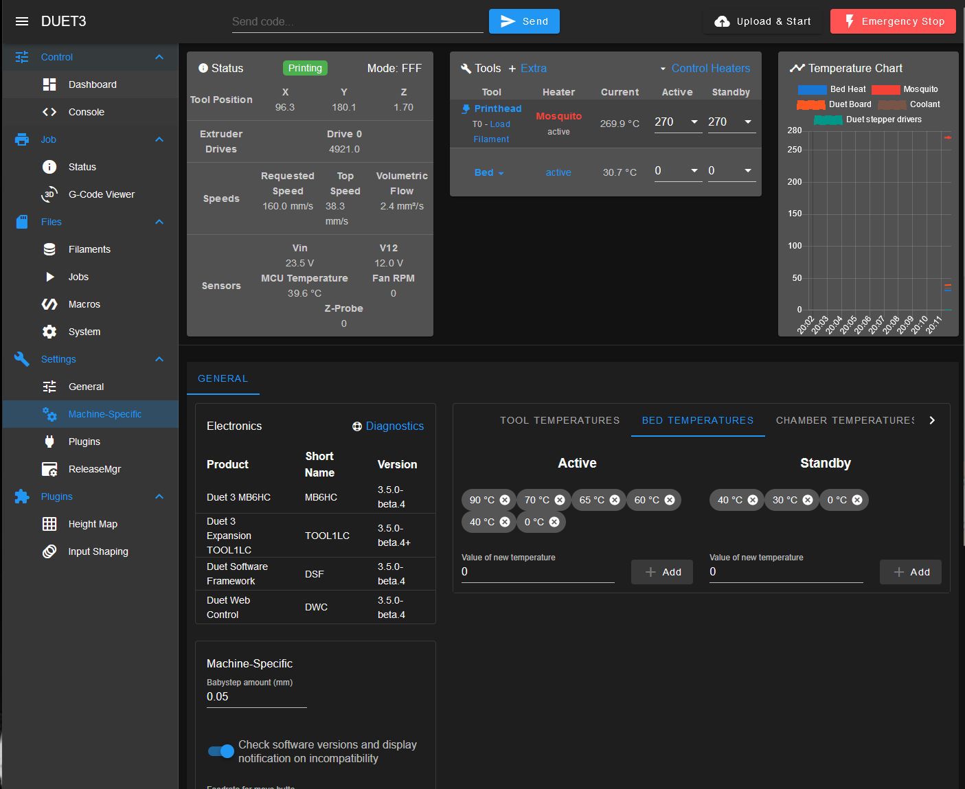
RE: presets on the dashboard don't match settingsposted in Duet Web Control
@chrishamm I see this on Safari and also on firefox. The firefox browser is on a PC, safari on MacOS. Same things on both.
-
RE: presets on the dashboard don't match settingsposted in Duet Web Control
@chrishamm, do you mean my config.g?
; Configuration file for Duet3 (firmware version 3.4 beta7)
; executed by the firmware on start-up
;
; --------------- Pin/connection Mapping Legend -------------------
; 0.out0      - Bed heater
; 0.out1
; 0.out2
; 0.out3
; 0.out4      - Radiator cooling fan - WC heatsink
; 0.out5
; 0.out6
; 0.out7
; 0.out8
; 0.out9      - Duet board cooling fan
; 0.out4.tach - Radiator cooling fan rpm wire - WC heatsink
; 0.out5.tach
; 0.out6.tach
; 0.io0.in
; 0.io1.in    - Emergency stop switch
; 0.io2.in    - Y max active low endstop switch
; 0.io3.in
; 0.io4.in
; 0.io5.in
; 0.io6.in
; 0.io7.in
; 0.io8.in
; 0.io0.out
; 0.io1.out
; 0.io2.out
; 0.io3.out
; 0.io4.out
; 0.io5.out
; 0.io6.out
; 0.io7.out
; 0.io8.out
; 0.servo, out10 (only on v0.5, not on v0.6)
; 0.pson
; 0.spi.cs0
; 0.spi.cs1
; 0.spi.cs2
; 0.spi.cs3
; 0.temp0      - Bed Thermistor
; 0.temp1
; 0.temp2
; 0.temp3      - Coolant Temp Sensor
; 0.mcu-temp   - MCU sensor
;
;----------Toolboard 1 (CAN ID#20)
; 20.0         - Accelerometer
; 20.out0      - Hotend Heater
; 20.out1      -
; 20.out2      - Parts cooler on printhead
; 20.out1.tach -
; 20.out2.tach -
; 20.io0.in    - Z probe type to bltouch current - Piezo future
; 20.io1.in    - X min active low endstop switch
; 20.io2.in    -
; 20.io3.in    -
; 20.io0.out   - GPIO port 0 on toolboard io0, servo mode - BLTouch Z-Probe
; 20.temp0     - Extruder Thermistor
; 20.temp1     -
; 20.button0   -
; 20.button1   -
;
; -----------------------------------------------------------------
;
; General preferences
M80 C"!pson"                      ; Declare the Power Pin (inverted for Meanwell)
M80                               ; Turn on the Power
G4 P2000                          ; Hold your Horses.
G90                               ; send absolute coordinates...
M83                               ; ...but relative extruder moves
G21                               ; Set units to Millimeters
M550 P"DUET3"                     ; set printer name
M575 P1 S1 B57600                 ; Set things up for the PanelDue

G4 S6                             ; Wait for toolboard to start
M584 X0.3 Y0.2 Z0.0:0.1:0.4 E20.0 ; set drive mapping to each axis
M669 K1                           ; Select CoreXY mode - New format

; Network
; M552 S1                         ; enable network
; M586 P0 S1                      ; enable HTTP
; M586 P1 S0                      ; disable FTP
; M586 P2 S0                      ; disable Telnet

; Drives
M569 P0.0 S0                    ; physical drive 0 goes backwards - Z Axis Left (1)
M569 P0.1 S0                    ; physical drive 1 goes backwards - Z Axis Right Back (2)
M569 P0.2 S0                    ; physical drive 2 goes backwards - Y Axis
M569 P0.3 S0                    ; physical drive 3 goes backwards - X Axis
M569 P0.4 S0                    ; physical drive 4 goes backwards - Z Axis Right Front (3)
M569 P20.0 S1                   ; physical drive 5 goes forwards - Extruder 1

; Set up three Z-axis location
M671 X-6:362:362 Y186:299:60 S5            ; Pivot Points at 1 - left, 2 - rear right and 3 - front right

M92 X200 Y200 Z800 E1299                  ; set steps per mm
M350 X16 Y16 Z16 E16 I1                    ; configure micro-stepping with interpolation
M566 X600.00 Y600.00 Z100.00 E240.00       ; set maximum instantaneous speed changes (mm/min)
M203 X16000.00 Y16000.00 Z400.00 E1200.00  ; set maximum speeds (mm/min)
M201 X4000.00 Y4000.00 Z400.00 E800.00     ; set accelerations (mm/s^2)
M906 X800 Y800 Z800 E800 I30               ; set motor currents (mA) and motor idle factor in percent*100

; Set up Stealthcop Parameters
; M569 P0.0 V40 H5
; M569 P0.1 V40 H5
; M569 P0.2 V40 H5
; M569 P0.3 V40 H5
; M569 P0.4 V40 H5
; M569 P20.0 V40 H5
; M915 X Y Z E T1

M84 S30                                    ; Set idle timeout

; Axis Limits
M208 X0 Y0 Z0 S1                           ; set axis minima
M208 X315 Y315 Z325 S0                     ; set axis maxima

; Endstops

M574 X1 S1 P"20.io1.in"                    ; X min active high endstop switch
M574 Y2 S1 P"0.io2.in"                     ; Y max active high endstop switch

; Z-Probe - BLTouch - *CURRENT*
M574 Z1 S2                                 ; set endstops controlled by probe
M558 P9 C"^20.io0.in" H5 F2000 T12000      ; set Z probe type to bltouch and the dive height + speeds (bltouch NEEDS pullup)
G31 P100 X0 Y-20 Z3.85                     ; set Z probe trigger value, offset and trigger height - 0.40MM NOZZLE FIXED Kv1

; Configure Heaters and Sensors
M308 S0 P"0.temp0" Y"thermistor" A"Bed Heat" T100000 B3950    ; Configure bed temperature sensor
M950 H0 C"0.out0" T0                                          ; Define heater 0 (bed heater) - bed_heat pin and Temp Sensor 0
M140 H0                                                       ; Map heated bed to heater 0
M143 H0 P0 S120 A2                                            ; set temperature limit for heater 0 to 120c

M308 S1 P"20.temp0" Y"pt1000" A"Mosquito"                     ; Configure extruder 1 temperature sensor - Mosquito
M950 H1 C"20.out0" T1                                         ; Define heater 1 (hot-end E0) to use the "20.out0" pin and Temp Sensor 1

M143 H1 S280 A2                                               ; set temperature limit for heater 1 to 280C

M308 S2 P"mcu-temp" Y"mcu-temp" A"Duet Board"                 ; Configure MCU sensor
M308 S3 P"temp3" Y"thermistor" T10000 B3988 A"Coolant"        ; Configure coolant sensor
M308 S4 P"drivers" Y"drivers" A"Duet stepper drivers"         ; defines sensor 4 as stepper driver temperature sensor

; Configure Fans
M950 F0 C"20.out2" Q100                 ; Define Fan_0 for use - Parts Cooler on Printhead - 5015 fan
M950 F1 C"0.out9" Q25000                ; Define Fan_1 for use - Duet board cooling fan
M950 F2 C"!0.out4+^0.out4.tach" Q25000  ; Define Fan_1 for use - Radiator cooling - WC heatsink. - PWM fan
M950 S0 C"20.io0.out"                   ; Define GPIO port 0 on IO0, servo mode - BLTouch Z-Probe - *CURRENT*
M950 J0 C"^!0.io1.in"                   ; Input 0 uses 0.io1.in pin, pullup enabled

; Fans
M106 P0 S0                        ; set fan 0. Parts Cooler on Printhead
M106 P1 H2:4 T40:70               ; Set fan 1. Manages Duet board fan.
M106 P2 H3 T35:50                 ; Set fan 1. Manages Radiator fan for water-cooled loop.

;Set PID values
M307 H0 R0.731 K0.271:0.000 D1.85 E1.35 S1.00 B0         ; disable bang-bang mode for the bed heater and set PWM limit
M307 H1 R2.839 K0.347:0.134 D6.69 E1.35 S1.00 B0 V23.8   ; disable bang-bang mode for the extruder heater and set PWM limit
; Pressure Advance
M572 D0 S0.08                             ; Set pressure advance to offset elasticity

; Dynamic Acceleration Adjustment and Non-linear
; M592 D0 A0.005 B0.0012 L0.2
 M593 P"ei2" F296.5 S0.005

; Set Movement Queue
M595 P100

; Set up Accelerometer
M955 P20.0 I12                      ; Accelerometer on toolboard, oriented counter clockwise 90 Enable for RRF 3.3 Stable

; Tools
M563 P0 S"Printhead" D0 H1 F0       ; define tool 0. Fan 0 operates with an active hot-end
G10 L1 P0 X0 Y0 Z0                  ; set tool 0 axis offsets - - - X15 Y18 - Bed 0,0
G10 P0 R0 S0                        ; set active and standby temperatures to 0C

; Emergency Stop
M574 S1 P"^!0.io1.in"               ; Define Emergency endstop - emergency stop switch condition
M581 P0 S1 T0                       ; Define action to be taken with activation of emergency stop switch

; Miscellaneous
T0                                  ; select first tool

M98 P"homeall.g"                    ; Home X
I see this on my screen...
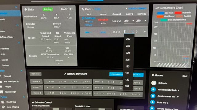
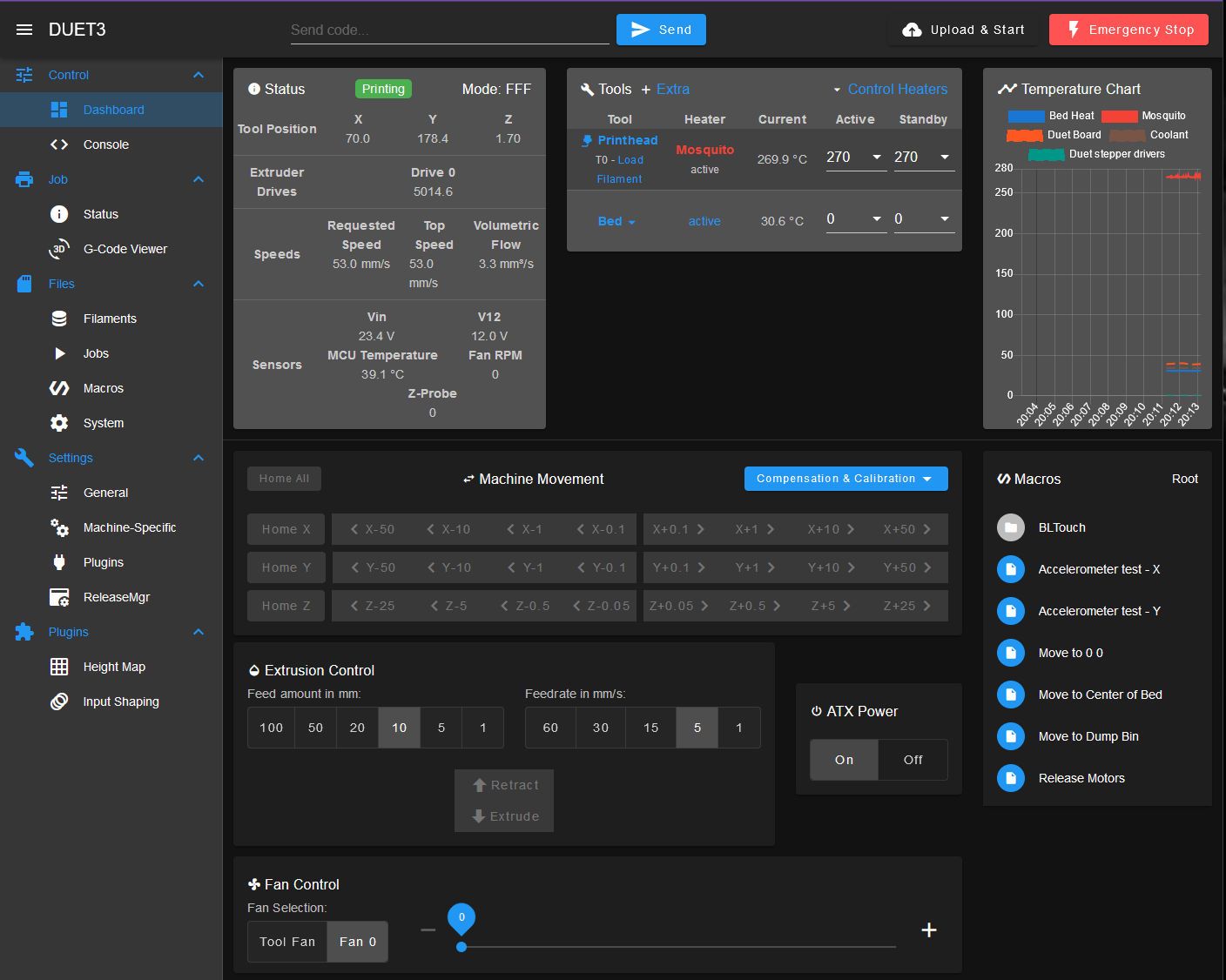
on the dashboard I see this....
the pulldown shows this....