• Tags
  • Documentation
  • Order
  • Register
  • Login
Duet3D Logo Duet3D
  • Tags
  • Documentation
  • Order
  • Register
  • Login

mesh bed compensation not applying correct corrections

Scheduled Pinned Locked Moved Unsolved
Tuning and tweaking
6
43
2.3k
Loading More Posts
  • Oldest to Newest
  • Newest to Oldest
  • Most Votes
Reply
  • Reply as topic
Log in to reply
This topic has been deleted. Only users with topic management privileges can see it.
  • ?
    A Former User
    last edited by 27 Jan 2020, 22:50

    i could be wrong, but i thought you should only need G28 and G29 S1 if the machine is reliable you'd only need to run that once, not for each print as well

    1 Reply Last reply Reply Quote 0
    • undefined
      necrorat
      last edited by 27 Jan 2020, 23:40

      i tried running just G29 S1 in the start Gcode, same behaviour

      1 Reply Last reply Reply Quote 0
      • undefined
        Phaedrux Moderator
        last edited by 28 Jan 2020, 00:20

        Perhaps you need to run G32 a few times to get the bed to level out perfectly?

        Z-Bot CoreXY Build | Thingiverse Profile

        1 Reply Last reply Reply Quote 0
        • undefined
          necrorat
          last edited by 28 Jan 2020, 00:57

          just done a cycle of 5 G32 commands and one after the other and i seem to have a consistent 0.100ish tilt, i do have 2 independent z axis motors could the correction not be applying itself correctly?

          28/01/2020, 00:55:40 G32
          Leadscrew adjustments made: -0.094 -0.111, points used 2, deviation before 0.103 after 0.000
          28/01/2020, 00:55:20 G32
          Leadscrew adjustments made: -0.104 -0.104, points used 2, deviation before 0.104 after 0.000
          28/01/2020, 00:55:01 G32
          Leadscrew adjustments made: -0.101 -0.104, points used 2, deviation before 0.103 after 0.000
          28/01/2020, 00:54:37 G32
          Leadscrew adjustments made: -0.104 -0.102, points used 2, deviation before 0.103 after 0.000
          28/01/2020, 00:54:14 G32
          Leadscrew adjustments made: -0.093 -0.100, points used 2, deviation before 0.097 after 0.000
          28/01/2020, 00:53:53 G32
          Leadscrew adjustments made: -0.122 -0.080, points used 2, deviation before 0.102 after 0.000

          1 Reply Last reply Reply Quote 0
          • undefined
            Phaedrux Moderator
            last edited by 28 Jan 2020, 18:04

            I'm not sure what to make of those results.

            Z-Bot CoreXY Build | Thingiverse Profile

            1 Reply Last reply Reply Quote 0
            • undefined
              SIam
              last edited by SIam 28 Jan 2020, 18:15

              M671 x-60:353 Y140:140 S2 ; leadscrew at left (connected to z) and right (connected to

              are you shure that your first leadscrew is on pos x-60 y 140
              and the second is on x353 y140 ???

              if yes than the limits are wrong

              ; Axis Limits
              M208 X0 Y0 Z-1 S1 ; set axis minima
              M208 X295 Y277 Z275 S0

              for example my working config with 3 leadscrews:

              M671 X0:380:0 Y52:190:327 S3 F1.0; Leitspindeln links und rechts von der X-Achse

              Hypercube-Evolution-Hybrid, Piezo Orion, Orbiter
              Duet WiFi 1.02 or later + DueX5
              RepRapFirmware for Duet 2 WiFi/Ethernet 3.4.0beta4 (2021-09-27 11:30:36)
              Duet WiFi Server: 1.26
              Duet Web Control 3.4.0beta4 (2021-09-27)

              1 Reply Last reply Reply Quote 0
              • undefined
                necrorat
                last edited by necrorat 28 Jan 2020, 18:41

                so the stated points are from the machine origin ie 00 the left leadscrew is to the left of the heat bed and the right leadscrew is to the right of the heat bed so the machine cant physically reach those points. should the m208 also have these figures in?

                undefined 1 Reply Last reply 28 Jan 2020, 19:01 Reply Quote 0
                • undefined
                  Phaedrux Moderator @necrorat
                  last edited by 28 Jan 2020, 19:01

                  @necrorat said in mesh bed compensation not applying correct corrections:

                  should the m208 also have these figures in?

                  No, M208 should define your reachable area. It's normal for the lead screws to be outside the print area. Your probe points should be as close as possible to the lead screws.

                  Z-Bot CoreXY Build | Thingiverse Profile

                  undefined 1 Reply Last reply 28 Jan 2020, 19:54 Reply Quote 0
                  • undefined
                    Veti
                    last edited by 28 Jan 2020, 19:15

                    i dont think there should be a G29 S1 in the bed.g

                    1 Reply Last reply Reply Quote 0
                    • undefined
                      Veti
                      last edited by 28 Jan 2020, 19:17

                      M557 X23:270 Y9:265 P2 ; define mesh grid

                      P2 will not result in a usable mesh.

                      try S15

                      1 Reply Last reply Reply Quote 1
                      • undefined
                        necrorat
                        last edited by necrorat 28 Jan 2020, 19:52

                        for the p parameter it was originally at 8 and behaved exactly the same. i am using two now to speed up iterations and to see if there is an improvement, so far the exactly the same behaviour despite the amount of probed points. as for the bed.g ill remove the G29 and see if that helps

                        1 Reply Last reply Reply Quote 0
                        • undefined
                          necrorat @Phaedrux
                          last edited by 28 Jan 2020, 19:54

                          @Phaedrux that was my understanding and have set them as such. the probe point is about 10mm in from the edge of the bed so as close as reasonably possible

                          1 Reply Last reply Reply Quote 0
                          • undefined
                            necrorat
                            last edited by necrorat 28 Jan 2020, 21:15

                            one further question when taking the measurements for the where the leadscrews are positioned should i be taking the measurements from the nozzle or from the probe? (nozzle is 0,0)

                            1 Reply Last reply Reply Quote 0
                            • undefined
                              Phaedrux Moderator
                              last edited by 28 Jan 2020, 22:27

                              I'm not sure I understand what you mean. The lead screws are fixed in relation to the bed, so their position is absolute. 0,0 is a point on the bed, the nozzle/probe/printhead is relative to that. The lead screw position would be relative to the 0,0 position in absolute coordinates.

                              Does that make sense?

                              Z-Bot CoreXY Build | Thingiverse Profile

                              undefined 1 Reply Last reply 28 Jan 2020, 22:37 Reply Quote 0
                              • undefined
                                necrorat @Phaedrux
                                last edited by 28 Jan 2020, 22:37

                                @Phaedrux so when i home my machine the print head moves to 0,0 which lines up with the printer nozzle being in the bottom left corner. what i wanted to check is that the bed compensation calculations where been done relative to the nozzle not the probe as the probe is offset approximately 23mm from the nozzle. so the above values would of been off but after digging and as you said the calcs are done from the nozzle for all intensive purposes and that is how i have it configured at the moment.

                                1 Reply Last reply Reply Quote 0
                                • undefined
                                  necrorat
                                  last edited by 31 Jan 2020, 00:04

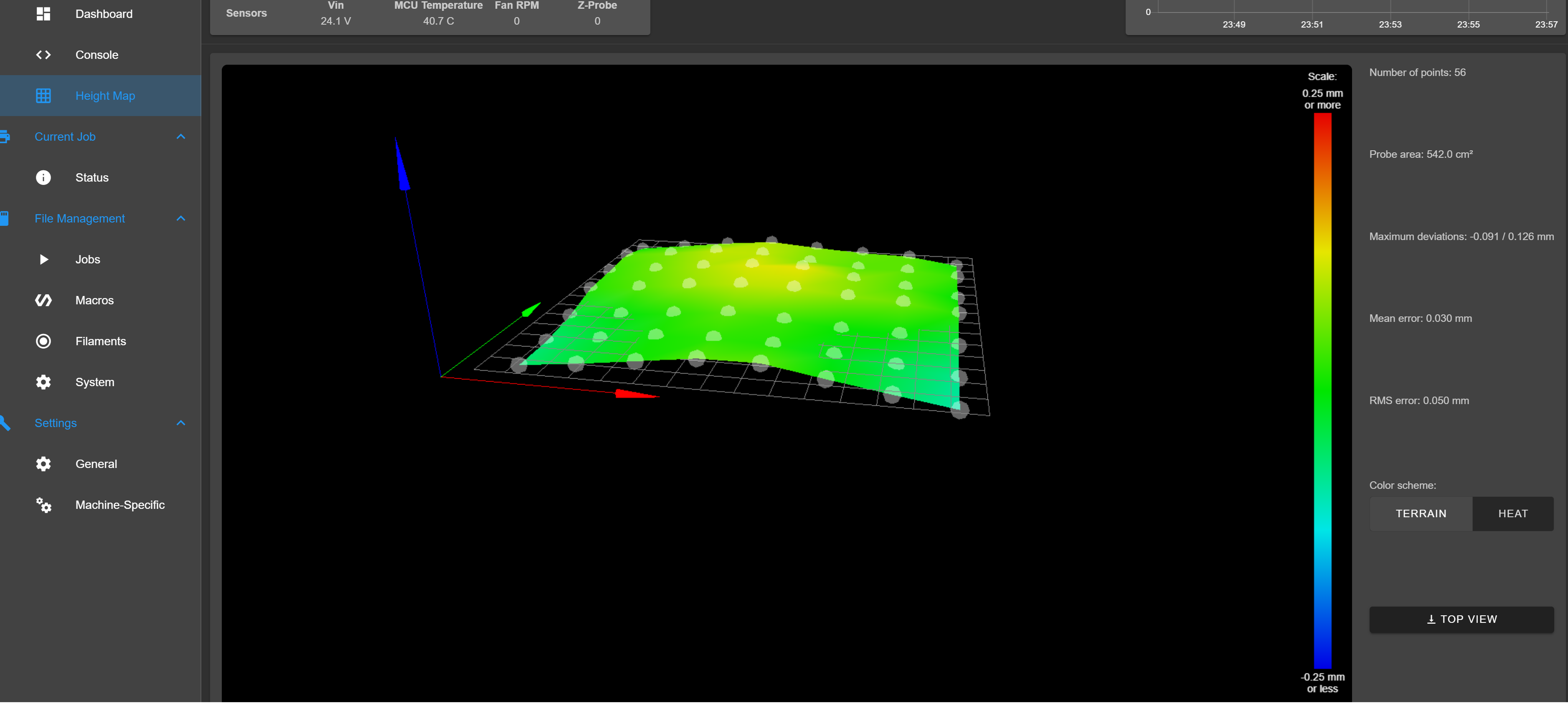
                                  so an update to the issue. spent all of this evening re checking that the machine is as square as reasonably possible and have levelled the bed to as close as i can get it to perfectly flat

                                  height map.png
                                  but now when i go to load up the height map it gives me the error:
                                  G29 S1
                                  Error: G29: Failed to load height map from file heightmap.csv: failed to read line from file

                                  at this point i dont really need mesh compensation as get ting very nice first layers without the mesh but for completions sake i want to get everything working as intended and iron out the few areas that are slightly more squashed than others on the first layer. should i try reducing the number of probed points to try and get it to accept the height map? or just any steers in the right direction would be highly appreciated.

                                  undefined 1 Reply Last reply 31 Jan 2020, 16:25 Reply Quote 0
                                  • undefined
                                    Phaedrux Moderator
                                    last edited by 31 Jan 2020, 00:22

                                    Can you upload that Height map. CSV?

                                    Z-Bot CoreXY Build | Thingiverse Profile

                                    undefined 1 Reply Last reply 31 Jan 2020, 00:25 Reply Quote 0
                                    • undefined
                                      necrorat @Phaedrux
                                      last edited by 31 Jan 2020, 00:25

                                      @Phaedrux heightmap.csv there you go mate, appreciate the help so far!

                                      1 Reply Last reply Reply Quote 0
                                      • undefined
                                        Phaedrux Moderator
                                        last edited by 31 Jan 2020, 03:56

                                        I don't see anything in particular wrong with that file. Try deleting it from the SD card and re-running G29

                                        Z-Bot CoreXY Build | Thingiverse Profile

                                        1 Reply Last reply Reply Quote 0
                                        • undefined
                                          necrorat
                                          last edited by 31 Jan 2020, 15:09

                                          so deleted the file and reduced the number of probe points and it seems to of accepted the file now,but it still seems to be not applying the mesh correctly. there are inconstant very small gaps between the extruded lines in a couple of patches on the bed so that leads me to believe that something i have borked up in my config. ive checked my extrusion multiplier and calibrated my e steps so at this stage it must be something in my config or associated files.

                                          1 Reply Last reply Reply Quote 0
                                          11 out of 43
                                          • First post
                                            11/43
                                            Last post
                                          Unless otherwise noted, all forum content is licensed under CC-BY-SA