fans not working
-
Hi,
I had just bought a fan for my 2nd tool head of my tool changer. I connected it and found that it's not working. In an attempt to know what's wrong, I stick the multimeter pins into the sockets and shorted them.
After going through the posts here, I found that the 1 amp fuse is blown. So I connected a jumper between the terminals.
Result : the always on fans are working.The three mosfets look fine with no damage.
So I went on to test the pwm fans in the web control. And here is the problem.I select the tool 0 and slide the fan slider to 100%, tool 0 part cooling fan works.
I select the tool 1 and do the same thing, still tool 0 part cooling fan turns and not the tool 1 part cooling fan.
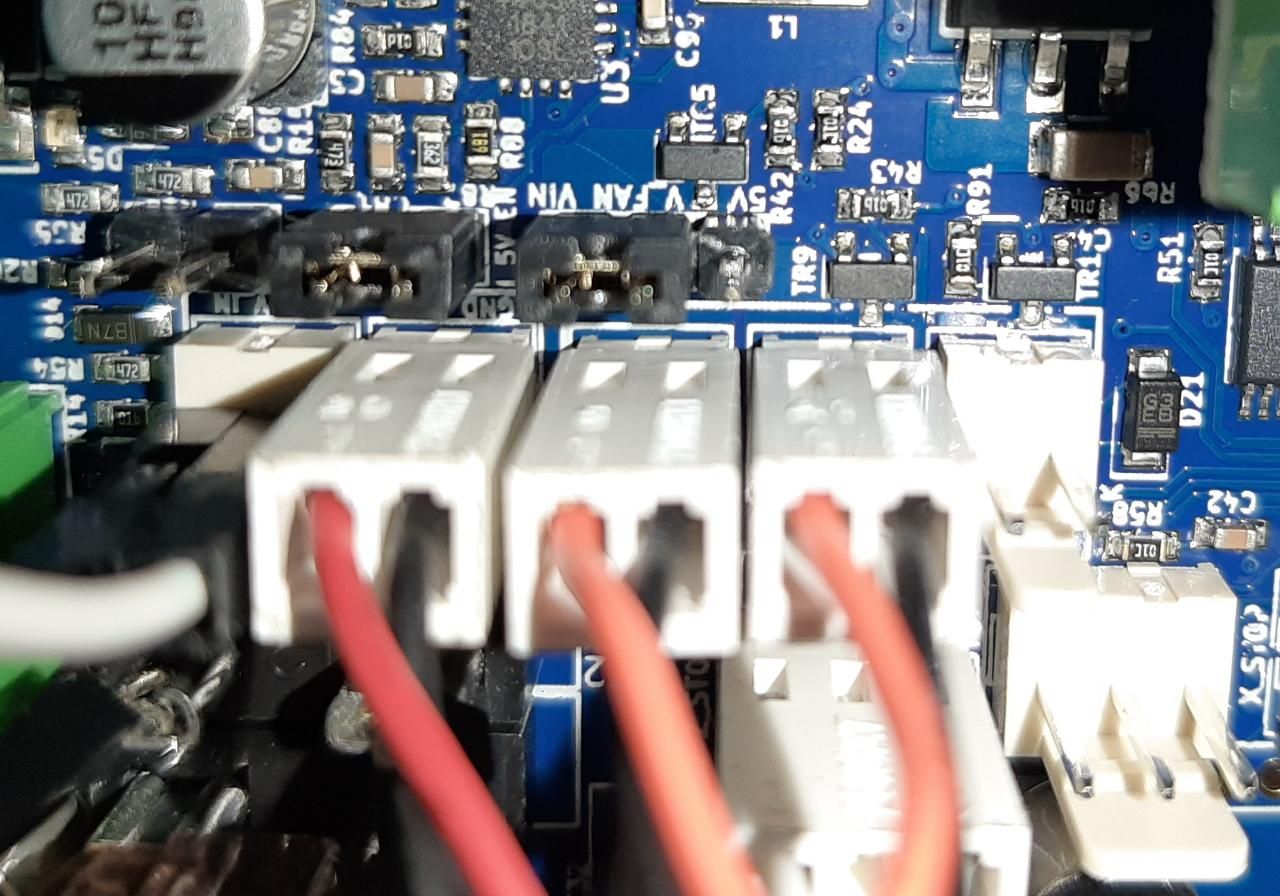
No matter what I do, I can't turn the tool 1 part cooling fan on.Wiring :
in the order of ports : [tool 0 hotend-always on] [tool 1 hotend - always on] [tool 0 part cooling fan] [tool 1 part cooling fan] [empty]Where am I going wrong and what might be the issue.
-
Can you post your config.g, please?
-
; Configurat; Configuration file for Duet WiFi / Ethernet ; executed by the firmware on start-up ; General preferences M111 S0 ; Debugging off G21 ; Work in millimetres G90 ; Send absolute coordinates... M83 ; ...but relative extruder moves M555 P2 ; Set firmware compatibility to look like Marlin ; Network M550 P"ToolChanger" ; Set machine name ;M587 S"ssid" P"password" ; WiFi Settings ;M552 S1 P"ssid" ; Enable WiFi Networking M552 S2 ; Enable Networking M586 P0 S1 ; Enable HTTP M586 P1 S0 ; Disable FTP M586 P2 S0 ; Disable Telnet M667 S1 ; Select CoreXY mode ; Endstops M574 X1 Y1 S3 ; Set X / Y endstop stall detection M574 Z1 S2 ; Set Z endstop probe M558 P7 X0 Y0 Z2 H3 F360 I0 T20000 ; Set Z probe type to switch, the axes for which it is used and the dive height + speeds G31 P200 X0 Y0 Z0 ; Set Z probe trigger value, offset and trigger height M557 X10:290 Y20:180 S40 ; Define mesh grid ; Drive direction M569 P0 S0 ; Drive 0 X M569 P1 S0 ; Drive 1 Y M569 P2 S1 ; Drive 2 Z M569 P3 S0 ; Drive 3 E0 M569 P4 S0 ; Drive 4 E1 M569 P5 S1 ; Drive 5 E2 M569 P6 S1 ; Drive 6 E3 M569 P7 S0 ; Drive 7 COUPLER M569 P8 S0 ; Drive 8 UNUSED M569 P9 S0 ; Drive 9 UNUSED M584 X0 Y1 Z2 C7 E3:4:5:6 ; Apply custom drive mapping M208 X-35:328.5 Y-49:243 Z0:300 C0:500 S0 ; Set axis maxima & minima M350 E8:8:8:8 C8 I0 ; Configure microstepping without interpolation M350 X16 Y16 Z16 I1 ; Configure microstepping with interpolation M92 X100 Y100 Z1600 C100 E417:417:417:417 ; Set steps per mm M566 X400 Y400 Z8 C2 E2:2:2:2 ; Set maximum instantaneous speed changes (mm/min) M203 X35000 Y35000 Z1200 C5000 E5000:5000:5000:5000 ; Set maximum speeds (mm/min) M201 X6000 Y6000 Z400 C500 E2500:2500:2500:2500 ; Set accelerations (mm/s^2) M906 X2000 Y2000 Z1330 C400 E1680:1680:1680:1680 I30 ; Set motor currents (mA) and motor idle factor in percent M84 S120 ; Set idle timeout ;Stall Detection M915 C S5 F0 H200 R4700 ; Coupler ;Stall Detection M915 X Y z S5 F0 H400 R4700 ; X / Y Axes ; Heaters M305 S"BED" P0 T100000 B4138 C0 ; Set thermistor M143 H0 S225 ; Set temperature limit for heater 0 to 225C M305 S"T0" P1 R4700 T100000 B4388 ; Set thermistor M143 H1 S300 ; Set temperature limit for heater 1 to 300C M305 S"T1" P2 R4700 T100000 B4388 ; Set thermistor M143 H2 S300 ; Set temperature limit for heater 2 to 300C M305 S"T2" P3 R4700 T100000 B4388 ;Set thermistor M143 H3 S300 ; Set temperature limit for heater 3 to 300C M305 S"T3" P4 R4700 T100000 B4388 ; Set thermistor M143 H4 S300 ; Set temperature limit for heater 4 to 300C ; Tools M563 P0 S"T0" D0 H1 ; Define tool 0 G10 P0 X0 Y0 Z0 ; Reset tool 0 axis offsets G10 P0 R0 S0 ; Reset initial tool 0 active and standby temperatures to 0C M563 P1 S"T1" D1 H2 ; Define tool 1 G10 P1 X0 Y0 Z0 ; Reset tool 1 axis offsets G10 P1 R0 S0 ; Reset initial tool 1 active and standby temperatures to 0C M563 P2 S"T2" D2 H3 ; Define tool 2 G10 P2 X0 Y0 Z0 ; Reset tool 2 axis offsets G10 P2 R0 S0 ; Reset initial tool 2 active and standby temperatures to 0C M563 P3 S"T3" D3 H4 ; Define tool 3 G10 P3 X0 Y0 Z0 ; Reset tool 3 axis offsets G10 P3 R0 S0 ; Reset initial tool 3 active and standby temperatures to 0C ; Fans M106 P0 S0 ; UNUSED M106 P1 S255 H1 T70 ; T0 HE M106 P2 S0 ; T0 PCF M106 P3 S255 H2 T70 ; T1 HE M106 P4 S0 ; T1 PCF M106 P5 S255 H3 T70 ; T2 HE M106 P6 S0 ; T2 PCF M106 P7 S255 H4 T70 ; T3 HE M106 P8 S0 ; T3 PCF M593 F50 ; cancel ringing at 50Hz (https://forum.e3d-online.com/threads/accelerometer-and-resonance-measurements-of-the-motion-system.3445/) ;M376 H15 ; bed compensation taper ;tool offsets G10 P0 X-9 Y39 Z-5 ; T0 G10 P1 X10 Y50 Z-58.45 ; T1 G10 P2 X-9 Y39 Z-5 ; T2 G10 P3 X-9 Y39 Z-5 ; T3 ;deselect tools T-1 ;M572 D0 S0.2 ; pressure advance T0 ;M572 D1 S0.2 ; pressure advance T1 ;M572 D2 S0.2 ; pressure advance T2 ;M572 D3 S0.2 ; pressure advance T3 -
Your hot end fans are setup as 1 3 5 7 (in M106 commands) but your tool definitions (M563) do not specify fans, so they are defaulting to 0 0 0 0. Add Fn to your M563s.
Also, put the fan definitions BEFORE the tool definitions.
-
How do you do that.
Excuse me. I am fairly new to this. -
@siriltejad Replace your fans and tools sections in config.g with this:
; Fans
M106 P0 S0						; UNUSED
M106 P1 S255 H1 T70					; T0 HE
M106 P2 S0						; T0 PCF
M106 P3 S255 H2 T70 					; T1 HE
M106 P4 S0						; T1 PCF
M106 P5 S255 H3 T70 					; T2 HE
M106 P6 S0 						; T2 PCF
M106 P7 S255 H4 T70					; T3 HE
M106 P8 S0						; T3 PCF

; Tools
M563 P0 S"T0" D0 H1 F1 					; Define tool 0
G10 P0 X0 Y0 Z0 					; Reset tool 0 axis offsets
G10 P0 R0 S0 						; Reset initial tool 0 active and standby temperatures to 0C

M563 P1 S"T1" D1 H2 F3					; Define tool 1
G10 P1 X0 Y0 Z0 					; Reset tool 1 axis offsets
G10 P1 R0 S0 						; Reset initial tool 1 active and standby temperatures to 0C

M563 P2 S"T2" D2 H3 F5					; Define tool 2
G10 P2 X0 Y0 Z0 					; Reset tool 2 axis offsets
G10 P2 R0 S0 						; Reset initial tool 2 active and standby temperatures to 0C

M563 P3 S"T3" D3 H4 F7					; Define tool 3
G10 P3 X0 Y0 Z0 					; Reset tool 3 axis offsets
G10 P3 R0 S0 						; Reset initial tool 3 active and standby temperatures to 0C
The way you have it defined, the fans should be connected to:
T0 Hot end fan should be connected to FAN1, part cooling fan to FAN2 on Duet
T1 Hot end fan should be connected to FAN3, part cooling fan to FAN4 on Duex
T2 Hot end fan should be connected to FAN5, part cooling fan to FAN6 on Duex
T3 Hot end fan should be connected to FAN7, part cooling fan to FAN8 on DuexSee https://duet3d.dozuki.com/Wiki/Duet_Wiring_Diagrams and https://duet3d.dozuki.com/Wiki/Duex_wiring_diagrams for fan pin locations.
How are you controlling the individual part cooling fans? Either you'll need the slicer to know turn it on, or you'll have to do it in your tpre[tool number].g files.
Ian
-
Thanks a lot Ian.
I did the connections as you mentioned.
Now I can control the hot end fan with the fan speed slider in the web gui. But not the part cooling fan.
The part cooling fan doesn't turn on. How do you control them through tpre0.g config file.The most sensible situation would be - we select the tool and the hotend fan should automatically kick in and we should control the part cooling fan through the slider or from the slicer.
-
@siriltejad For each tool, you want to turn the part fan on in t[tool_number]pre.g, and turn it off in t[tool_number]post.g. The part cooling fans are not bound to the tools, so you have to command them specifically. You may be able to set up your slicer to do this, but I think most people here agree that it's best to let the firmware do it.
To control the fans, you need to send an M106 command, eg to turn the T0 PCF on 100%:
M106 P2 S255
or off with
M106 P2 S0Ian
Bed-slinger - Mini5+ WiFi/1LC | RRP Fisher v1 - D2 WiFi | Polargraph - D2 WiFi | TronXY X5S - 6HC/Roto | CNC router - 6HC | Tractus3D T1250 - D2 Eth
-
@droftarts said in fans not working:
@siriltejad For each tool, you want to turn the part fan on in t[tool_number]pre.g, and turn it off in t[tool_number]post.g. The part cooling fans are not bound to the tools, so you have to command them specifically. You may be able to set up your slicer to do this, but I think most people here agree that it's best to let the firmware do it.
To control the fans, you need to send an M106 command, eg to turn the T0 PCF on 100%:
M106 P2 S255
or off with
M106 P2 S0Ian
The best way to turn the part cooling fan on in tpost#.g is to use M106 R2 without a P parameter. That will restore the speed to the last value that the slicer commanded, assuming that you have set up the F parameters correctly in your M563 commands.
-
Thank you all.
I got the fans issue figured out now.