Ender 5 + Hemera + BL Touch
-
; bed.g
; called to perform automatic bed compensation via G32
;
; generated by RepRapFirmware Configuration Tool v2.1.8 on Sun Feb 02 2020 11:21:35 GMT-0600 (Central Standard Time)
M561 ; clear any bed transform
G29 ; probe the bed and enable compensation -
I am finding very weird results with this Duet DWC. It seems that even if I make a change I need to hit the emergency stop for the board to reboot and then actually use the changes. I set the mesh limit and it ignores them now (even though it was using them before). Struggling to find consistent behavior so I can trust this thing. I also noticed even though I uploaded a new reprap config the config.g was still unchanged so I had to again hit the emergency stop to force a reboot. I fail to believe this is how this thing is intended to work.
-
@mitch said in Ender 5 + Hemera + BL Touch:
I set the mesh limit and it ignores them now (even though it was using them before).
your bed just calls mesh grid compensation.
the configurator does not generate a proper bed.g for that anymore since it is depricated.
so the values you have put in in the dwc will be ignored. -
Ok, as a new user how do I know what is depreciated and what isn't? Not being sarcastic, seriously, how do I know what to trust will use settings and what will attempt to damage my printer?
Do I need to go in and manually update a bed.g? If it is depreciated what is used instead? I just want to make sure everything is functioning safely so I can be assured when I attempt to print it won't try to go off and slam into a limit or rip my BLtouch off the mount.
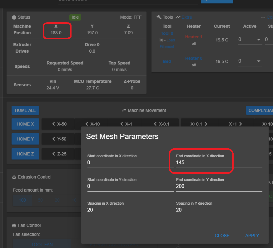
I set the limit down to 145 and it seemed to have an impact. Not that it used 145 as a limit but it didn't try to go off the bed with the sensor so something changed. The screen capture is from a completed mesh bed level. The final position was at 183? If I subtract 43 from 183 that gives me 140. -43mm was my x offset. Do I have my signs wrong on my BLTouch offset positions?
I have calculated the BLtouch offset to be:
Probe X Offset = -43mm (43 mm to the left of the head)
Probe Y Offset = 3mm (3 mm behind the head)
-
it says so in a big headline in the configuration tool
Note: 3/4/5 Point Bed Compensation is deprecated. It has been replaced with the new Mesh Bed Compensation.
you just use mesh compensation and not bed compensation.
from your picture
20mm space starting at 0
7*20=140+ 43mm offset = 183 -
@mitch said in Ender 5 + Hemera + BL Touch:
; bed.g
; called to perform automatic bed compensation via G32
;
; generated by RepRapFirmware Configuration Tool v2.1.8 on Sun Feb 02 2020 11:21:35 GMT-0600 (Central Standard Time)
M561 ; clear any bed transform
G29 ; probe the bed and enable compensationSo in your case, G32 is the same as running G29.
If you set the probing grid using the DWC popup box I don't think that it will change the values you have set in config.g so you should modify your config.g M557 command to use the grid size you need. That way it will persist between power cycles.
-
@Veti said in Ender 5 + Hemera + BL Touch:
it says so in a big headline in the configuration tool
Note: 3/4/5 Point Bed Compensation is deprecated. It has been replaced with the new Mesh Bed Compensation.
you just use mesh compensation and not bed compensation.
from your picture
20mm space starting at 0
7*20=140+ 43mm offset = 183Yes, which is why I was running Mesh Bed Compensation via the menu and still getting an overshoot on my sensor. The assumption is if you define the limit to be 145 it would actually stop at 145 and not keep trucking past it.
Are you trying to say that "Point Bed Compensation" (which yes I saw the warning sign) is the same thing as "True Bed Leveling G32"? Look, I know you think this is all obvious. But it is not. Which is why I am asking for help. In either case, my question is about the Mesh Bed Comp and the limits. I think the next poster answered the question with an actionable response. ty,
-
@Phaedrux said in Ender 5 + Hemera + BL Touch:
M557
What you said makes perfect sense.... but still unanticipated result for me.
I verified my Config.g already was defined as:
; Z-Probe
M950 S0 C"exp.heater4"                                 ; create servo pin 0 for BLTouch
M558 P9 C"zprobe.in+zprobe.mod" H5 F120 T6000          ; set Z probe type to bltouch and the dive height + speeds
G31 P500 X-43 Y3 Z2.5                                  ; set Z probe trigger value, offset and trigger height
M557 X0:180 Y0:195 S20                                 ; define mesh grid
So that means the tool should not attempt to exceed the 180mm position in the Y direction. I uploaded a file to print and when the G29 command was executed to do ABL. It went past the 180mm mark and attempted to probe one more time.
So to get on the same page. When we specify this grid. Are we talking tool position or probe position? In marlin everything was with respect to the tool position and it used the offsets defined for the probe as needed.
-
Yes, it's a little different than marlin.
M557 X0:180 looks correct to me. It's the position that the probe can actually reach. So if the axis is 220mm long, and your probe offset is -40, 180 should be the farthest the probe can actually reach.
Same for the Y axis values you have.
What do you currently have for steps per mm and microstepping values?
If you tell it to move 10mm, is it actually moving 10mm? -
yes, steps measure correct. I tell it to step 10mm it moves 10mm.
So....
I went into config.g and changed the offset to be positive.
x offset = 43mm
y offset = -3mmI set the mesh limit to the bed limit
x=180
y = 200Now everything seems to work fine. The system probes the bed evenly and doesn't attempt to move the probe off the bed at any time.
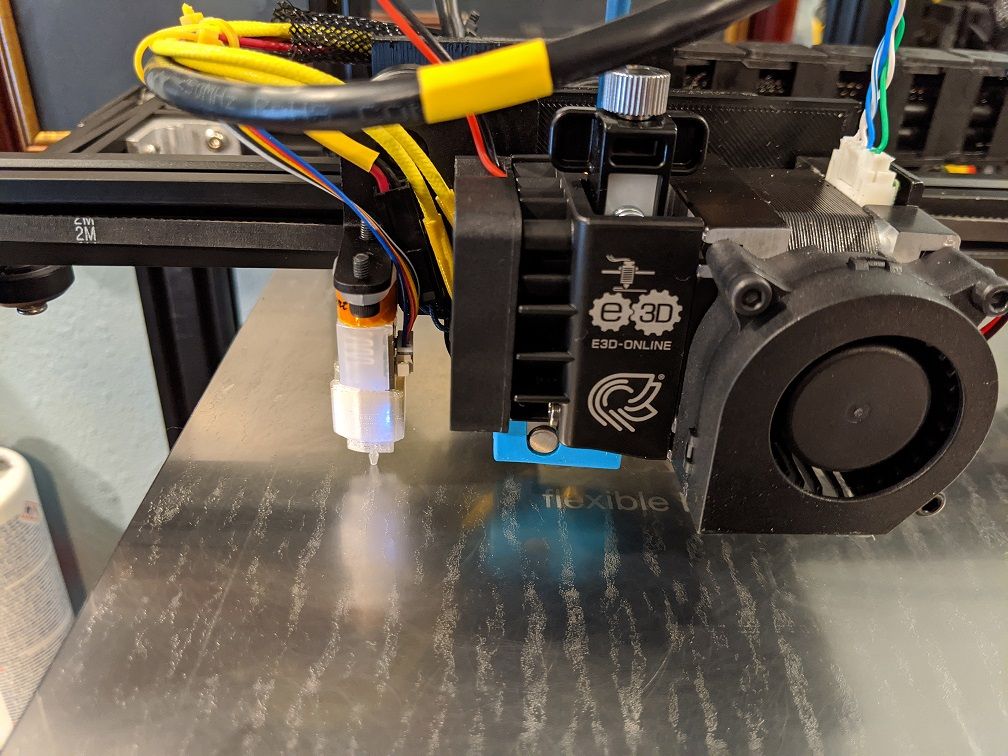
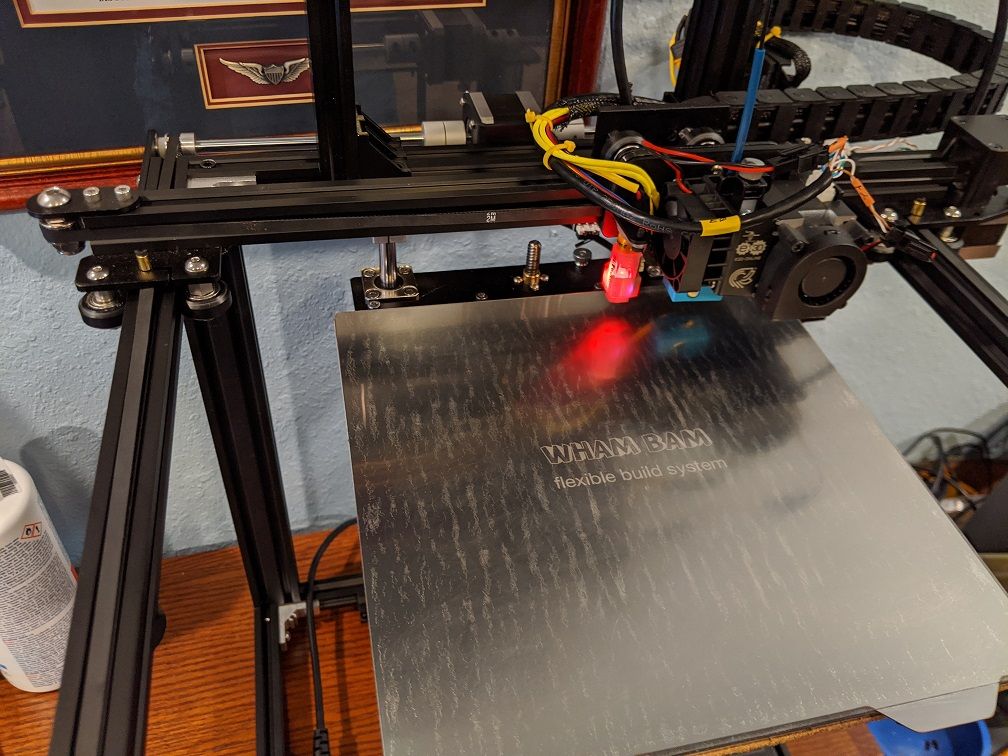
Perhaps the issue is that coordinate system used for the BLTouch offset? You can see a pic of my mounting. I understand that to be to the left of the head (neagative). The origin is in the back right of the printer. Would that make the sign of the offsets opposite (positive instead of negative)? I have always had the offset negative in marlin when mounted on the left side like this.
; Z-Probe
M950 S0 C"exp.heater4"                                 ; create servo pin 0 for BLTouch
M558 P9 C"zprobe.in+zprobe.mod" H5 F120 T6000          ; set Z probe type to bltouch and the dive height + speeds
G31 P500 X43 Y3 Z2.5                                  ; set Z probe trigger value, offset and trigger height
M557 X0:180 Y0:195 S20                                 ; define mesh grid
The origin 0,0 is the back right of the printer:
Yep, tried to print and the print is 180 from what it used to do with the creality board. I guess I could set the stops to be at the high end and then reverse the motor directions to put the origin at the bottom left or is it fine how it is?
-
@mitch said in Ender 5 + Hemera + BL Touch:
The origin is in the back right of the printer.
Yeah that would explain it
I think that has been noted before with the Ender 5.
Personally I would want to maintain a left handed coordinate system, but as long as things are not mirrored it's not really a big problem. So up to you.
-
@mitch said in Ender 5 + Hemera + BL Touch:
I could set the stops to be at the high end
Just a thing to think about: end stops serve the sole purpose to put the head at a known position. With this knowledge, you can steer the nozzle to whatever position you like and declare that as the origin of your coordinate system. This can be any corner or the center of the bed, as well. That is, end stops and the origin of your coordinate system don’t need to match.
-
Thanks,
Right now it seems to work with the origin being to the back right. I now what I need to flip to change it around. If most ender users are going to have it in the bottom left I will swap over to keep my config files similar as not to cause confusion the next time I need help with an issue.
thanks for all the help. I will post a final config file once it is swapped for the next person to start with.
I think the jerk value needs to be reduced as it is printing a little rough.
-
Mitch, Thank you very much for your trailed discussion, I am considering moving away from the ender silent board into a duet WiFi.
I have a suggestion for you to recover some of the lost dimensions on your print area: Have you see the Ender 5 Crossbar Relocation at thingiverse? It is a simple print and and easy modification to recover some of the lost space.
https://www.thingiverse.com/thing:3876601
I have a question, what screen did you use with the Duet Wifi?
Thanks
Daniel -
Thanks for the thingaverse link. I will check that out.
I did make some silly mistakes getting this up and running but thanks to those that replied to this thread I was able to get back on track. I am sure I won't be the last to make these errors so at least someone can stumble on this thread to work through similar issues.
As far as a display, I don't currently use one. I have a paneldue 7i on order but I think I am going to mainly use the web interface.
I have my setup running from a dedicated 2.5amp USB power supply from an old raspberry pi along with a relay that switches the main 24VDC power on/off. I still need to do some research to determine if the 2.5A supply will be enough after I add the 7i panel.
I am also not crazy about the idea of having the display on all of the time so I may put a switch on the display to shut it off when I am monitoring remote.
I was previously using octoprint with a raspberry pi and it was a great setup. If you add a pimironi on/off shim you can set the system to completely shutdown after a print which I currently cannot do with the duet2 and I miss the camera features I had with the octoprint that I no longer have with the Duet unless I add a pi back in the mix.
-
@mitch said in Ender 5 + Hemera + BL Touch:
I am also not crazy about the idea of having the display on all of the time so I may put a switch on the display to shut it off when I am monitoring remote.
2.5 might be enough. Might need one of the larger 5a bricks.
The PanelDue does have a setting to turn off the backlight when idle. So that might be an option instead of a switch to turn it off completely. But if you did want to go for a switch that would be fine. Others have used that as a way to disable the display at trade shows and the like where you don't want stray fingers poking at it.
-
@mitch said in Ender 5 + Hemera + BL Touch:
I am also not crazy about the idea of having the display on all of the time so I may put a switch on the display to shut it off when I am monitoring remote.
I've done this a lot, and:
- Powering it off has never disrupted anything.
- Powering it on, it always cleanly connects.