RRF3 BLtouch setup
-
@PaulHew Hi Paul, thanks!
When I look at the guide I linked to the M950 command has one of the EX pins: M950 S0 C"exp.heater3"
On yours it says "^zprobe.mod" but that's because it's on a maestro so that makes sense.
Other than that you also added the deployprobe,g and retractprobe.g macros right? -
@PaulHew said in RRF3 BLtouch setup:
Does this help?
This is for my Maestro; Z-Probe
M558 P9 C"zprobe.in" H5 F120 T6000 A10 R0.75 S0.02 ; set Z probe type to bltouch and the dive height + speeds
M950 S0 C"^zprobe.mod" ; create servo pin 0 for BLTouch
G31 P500 X42 Y-1 Z1.438 ; set Z probe trigger value, offset and trigger heightYou have the ^ in the wrong place. It should be:
M558 P9 C"^zprobe.in" H5 F120 T6000 A10 R0.75 S0.02 ; set Z probe type to bltouch and the dive height + speeds
M950 S0 C"zprobe.mod" ; create servo pin 0 for BLTouchNewer BLTouch variants won't work without the ^ in front of zprobe.in in the M558 command (or an external pullup resistor).
-
thanks @dc42 so if I understand correctly if I do the following it should work.
on RRF3
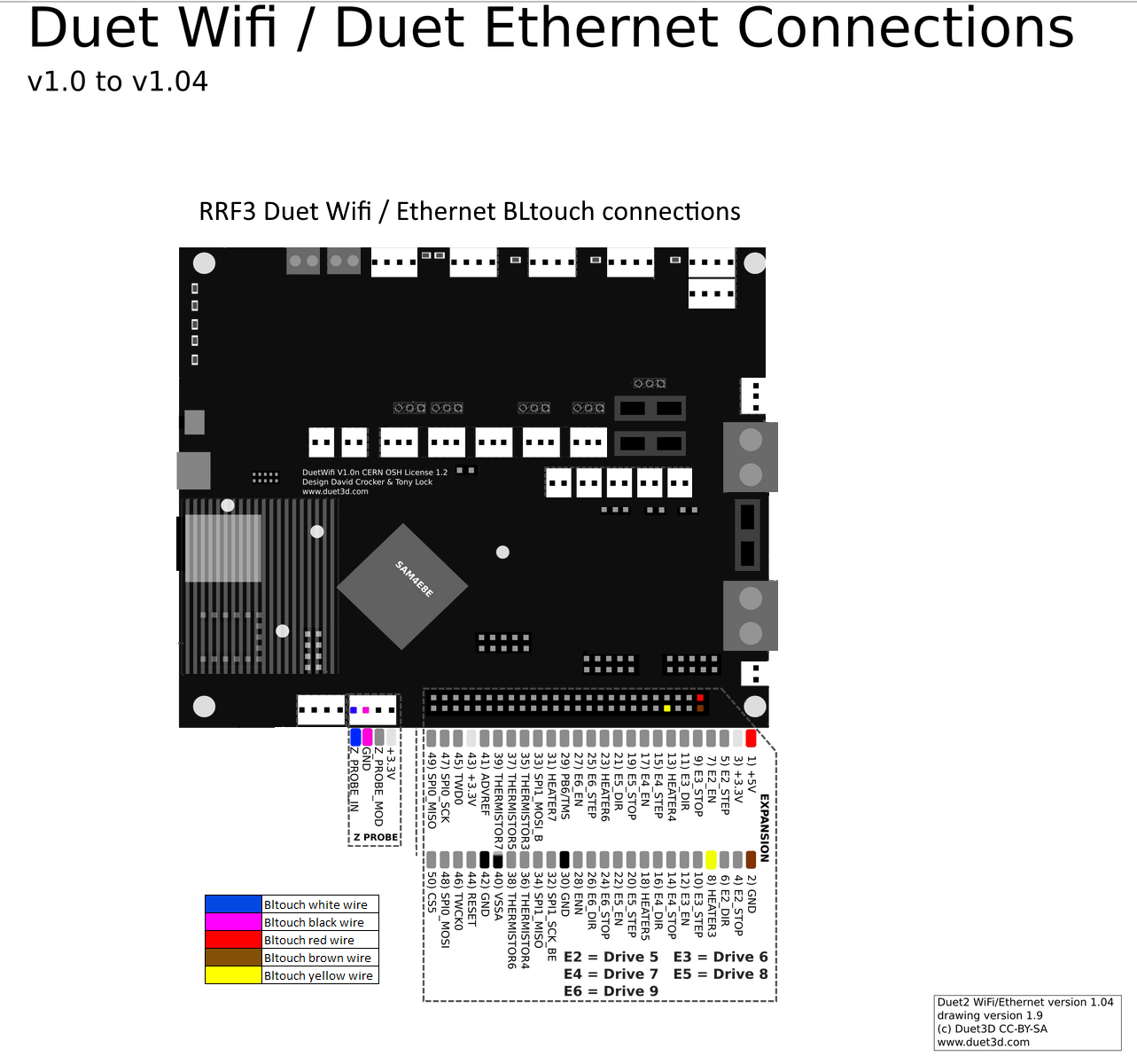
STEP 1: Connect the bltouch like below
(I drew a little scheme)

STEP 2: Add the following to config.g
M558 P9 C"^zprobe.in" H5 F120 T6000 A10 R0.75 S0.02 ; set Z probe type to bltouch and the dive height + speeds
M950 S0 C"exp.heater3" ; create servo pin 0 for BLTouch on exp.heater3
G31 P500 X42 Y-1 Z1.438 ; set Z probe trigger value, offset and trigger height
STEP 3: add macro files for deployprobe.g and retractprobe.g '
deployprobe.g
M280 P0 S10 ; deploy BLTouchretractprobe.g
M280 P0 S90 ; retract BLTouchAnything else that I'm overlooking? (I just want to be really sure I don't break anything
 )
) -
Your deployprobe.g and retracprobe.g commands would be correct for RRF2 but for RRF3 they must be changed to M280 P0 S10 in deplyprobe.g, and M280 P0 S90 in retractprobe.g.
The correct XYZ parameters in the G31 command will depend on the geometry of your hot end.
-
Thanks a lot for the help @dc42 , I adjusted the probe macros.
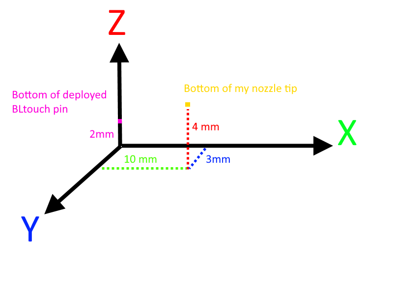
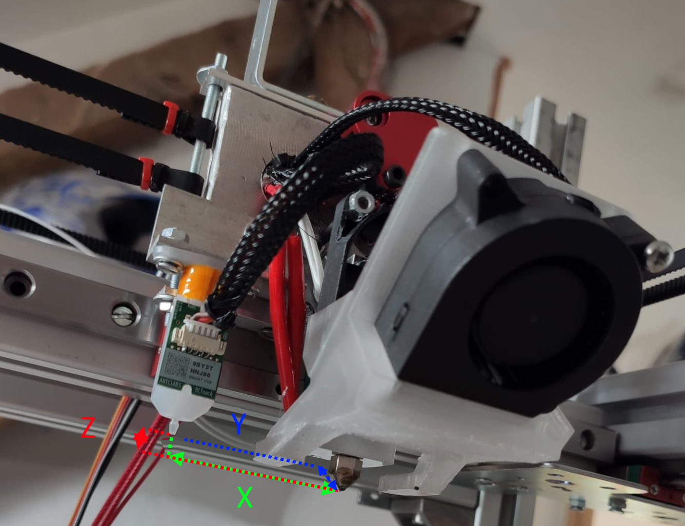
Looked up some more info on the G31 command and I think I understand that one but just to make sure, the image below is my printhead.
I drew this dimension to represent it and make sure these parameters are correct (just example values, not real ones)
G31 P500 X-10 Y-3 Z2Z= 4 - 2


-
The way you've drawn it, you have a left handed coordinate system. But if the Y arrow represents the direction in which the bed moves, then it's really right handed so that's OK. In which case, those G31 values look OK. You will need to measure the Z value, see https://duet3d.dozuki.com/Wiki/Test_and_calibrate_the_Z_probe.
-
@dc42 Not sure if I understand the left / right hand thing but yeah Y is how the bed would move on a i3 style printer. In my case the head moves in X & Y and the bed moves for Z.
-
See here for a walk through of how to measure the probe offsets for G31 in X Y Z.
https://duet3d.dozuki.com/Guide/Ender+3+Pro+and+Duet+Maestro+Guide+Part+5:+Upgrades/54#s230
-
@Phaedrux thanks! That's what I was looking for but couldn't find.
-
