Unable to correctly configure througt RRF config Tool
-
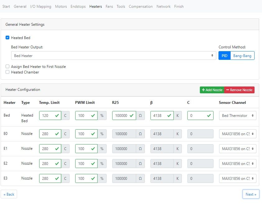
@IngPaoloFrancia The PanelDue enumerates the displayed heaters from the first used heater to the last, rather than what is in the config.g, unfortunately. Because you have defined your heaters on Heated bed (H0), E0 (H1), E1 (H2), E3 (H4) and E4 (H5), while the DWC shows this correctly, the PanelDue shows the missing E2 (H3) heater. It's just a limitation of the display, unfortunately. You then get a bit of a display glitch when showing more than 5 heaters.
To get the PanelDue to display correctly, you need to use consecutive heater connections. If your bed is powered by an SSR, rather than using the actual bed heater terminal, you could move all heater connections to the Duex, with bed on E2, hot ends on E3, E4, E5, E6. Otherwise it will be better to have the heaters on Bed (H0), E0 (H1), E1 (H2), E2 (H3), E3 (H4). Either of these options will display correctly on the PanelDue.
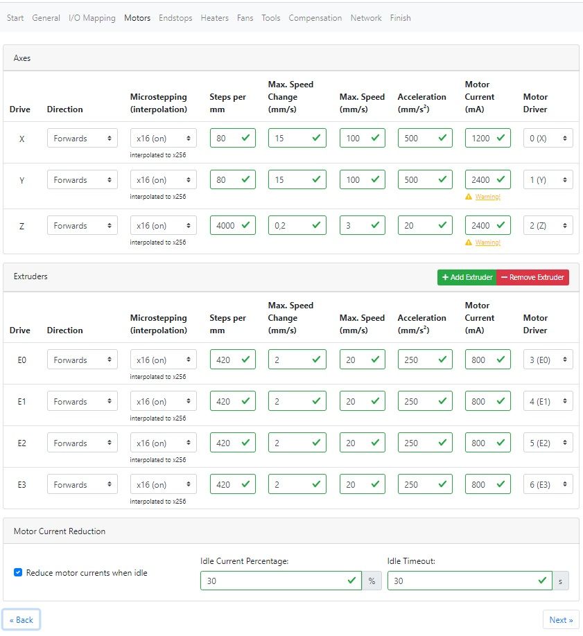
One final thing; you have set your motor driver currents on Y and Z to 2400mA, while X is on 1200mA. If you have two motors wired in series on each of Y and Z, you do not need to double the current; the motors will get very hot if not rated for 2.4A. You only have to double current if they are wired in parallel. If you keep 2400mA, the Duet will need additional cooling, best achieved with a fan blowing on the back of the PCB.
Ian
-
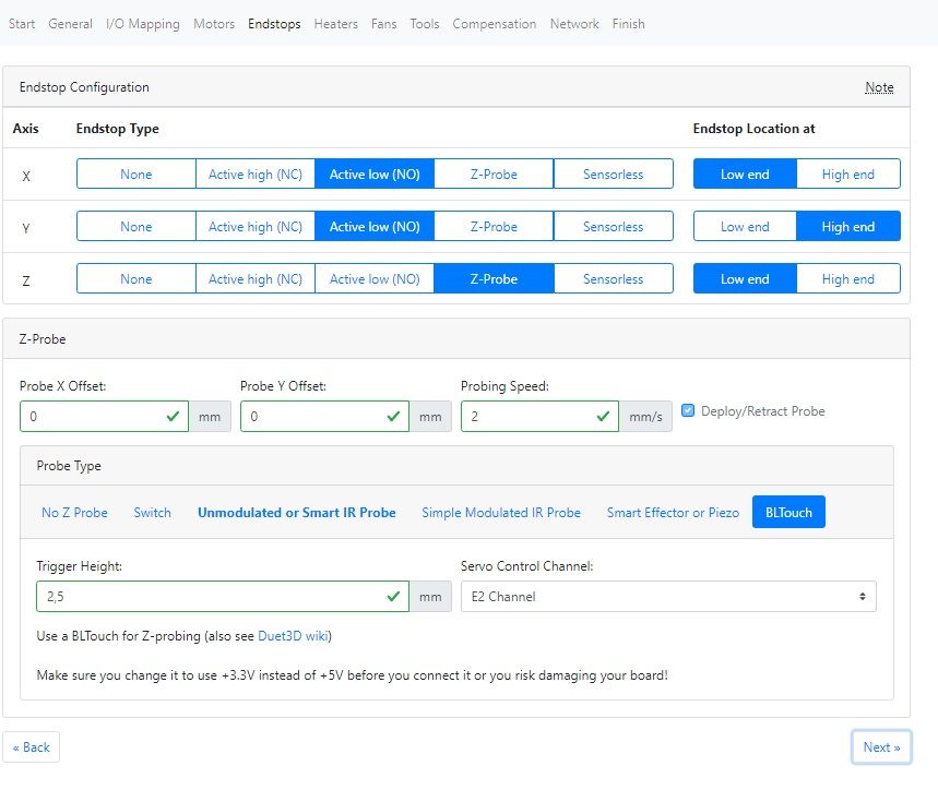
@droftarts Dear Ian thanks for the timely response, now I understand why I could not correctly configure the tools on the Display. As you suggest I will connect the bed heater to channel E2 so all the heaters will be in sequence on the DUEX5. For the BLTouch I have not found connection schemes recommended to the Probe In connector of the Duet Ethernet and I have read about some problems of compatibility of the timing of the control of this port with the BLTouch. Would it be possible to use the PWM signal of one of these heaters: H0, E0, E1? Where could I connect since there are no specific connectors on the Duet for these PWM channels?
Thanks for reminding me that I made a big mistake by increasing the driving current of the motors in series.
Regards
Paul -
@infiniteloop Hi, the printer we are making has a print volume of 500mmx500mmx500mm but the external size as you can imagine is much larger (about 0.35 cubic meters). Our target is to print Peek and Carbon Fiber charged polymers for professional application. This is the reason for thermocouples on nozzles , a powerfull Bed heater driven by SSR device, and also water cooling of the extruders. The heating of the printing chamber and its control will be another problem to be solved.
As we say here: we cross our fingers!
Regards
Paul -
@IngPaoloFrancia Sorry, when I suggested moving all heaters to the Duex, I forgot about the BLTouch!
For the BLTouch, the white (signal) and black (GND) wires should already be connected to 'IN' and 'GND' on the Duet ZProbe connector. In RepRapFirmware 2, there's no other way of doing this. In RepRapFirmware 3 you can specify for the signal to connect to any of the temperature sensing inputs.
I was mistaken about the BLTouch servo PWM connection. You can't use the E0, or E1 pins for BLTouch servo PWM, as they are at VIN (12/24V) so would fry the BLTouch, which takes 5V! Actually, it is possible to use them, but you would need to be sure to use the negative pin only, and add a pullup resistor to +5V. It's easier to use the servo PWM pins on the Duex, or the Duet expansion header if no Duex, which correctly supplies 5V PWM.
However, in your case, you have just moved all the heaters to the Duex heater outputs, so now there is no free PWM pin for the BLTouch! So I think a better solution is to move the heated bed SSR control back to E1 (H2) on the Duet. Then have your four hot ends on E2 (H3), E3 (H4), E4 (H5) and E5 (H6). This leaves E6 (H7) available for the BLTouch.
Let me know if you want help to get the config correct.
Ian
-
@droftarts
555/5000
Hi Ian I am very sorry that there are all the constraints you have indicated to me. The obligatory way seems to me the one you advise me: "So I think a better solution is to move the heated bed SSR control back to E1 (H2) on the Duet. Then have your four hot ends on E2 (H3), E3 ( H4), E4 (H5) and E5 (H6). This leaves E6 (H7) available for the BLTouch "
I would like to receive coherent .g and .json files for this solution. I'll let you know if this configuration also solves the display problems.
Thank you very much for this special support.
Paolo Francia -
@IngPaoloFrancia said in Unable to correctly configure througt RRF config Tool:
As we say here: we cross our fingers!
So we say here. Water cooling the cold side of the hot end is a good idea, it makes printing at high extrusion temperatures much more reliable, especially on larger retractions (which you’ll need with your bowden set-up). BTW: if you want a heated chamber, did you think about water cooling for the steppers, too? At 80°C, it is still not necessary on my machine, but just in case I want to go higher, I’ve at least provided a pump, hoses and connectors to let the waters flow

-
@infiniteloop Thanks I'll keep your suggestion in mind. Having already the pump and the water-air heat exchanger is a good idea to consider the circulation of water for the benefit of the motors.
regards
Paolo Francia -
the thing that leaves me very perplexed in reading this post, that a card that is so professional in the end, has all these limitations that do not allow easy programming regardless of the configuration I expected it was just a matter of applying the right positions to ensure that the channels you want to use are activated based on the design and functional needs of a printer.
-
Paolo has set a number of constraints to the implementation, and the scale of the machine is close what the Duet 2 can support, which has led to the limitations. Namely:
- Using 5 heaters out of a maximum of 8
- Using 7 motor axes, plus an extra axis for BLTouch, out of a maximum of 10
- Specific display requirements on the PanelDue. This is a limitation of the PanelDue, not Duet, but requires the heaters to be connected consecutively
- Paolo asked for all hot ends be connected to Duex (see the pdf attached to his posts)
- Using RepRapFirmware 2, rather than RepRapFirmware 3, limits choices a little.
I made an error in suggesting that the BLTouch servo PWM could be connected to the Duet, and subsequently all heaters could be connected to the Duex. However, once the initial configuration has been done, I don't see any problem, and while connections to the Duet may not be EXACTLY as Paolo first specified, it will work as intended.
The PanelDue is the main limitation, forcing a particular connection order for the heaters. It's at its limit showing 5 heaters; it wasn't designed for more. For complex printers, I'd recommend removing the PanelDue, and using an Android tablet or something similar mounted on the printer. This would provide the full Duet Web Console, rather than the limited display of the PanelDue, and allow more varied connections. But that's not what Paolo asked for.
For more complex machines/projects, Duet 3 + expansion board is probably a better choice now than Duet 2, but it is still maturing as a product. But again, that's not what Paolo specified.
I would describe the Duet is a 'prosumer' controller card. It isn't competing with the professional setups from Fanuc, Haas or Siemens, or have the complexity of a Linux CNC implementation. It also doesn't have their price tag, both in upfront or support cost!
I'm actually struggling to find any other product that is as flexible and extensible as Duet in the same price range; if you know of any please do let me know. We have a comparison chart with other 32-bit controller boards here: https://duet3d.dozuki.com/Wiki/Comparison_of_Duets_vs._other_32-bit_controller_boards
Ian
-
@IngPaoloFrancia said in Unable to correctly configure througt RRF config Tool:
I would like to receive coherent .g and .json files for this solution. I'll let you know if this configuration also solves the display problems.
I can't change the heater mapping in your config.json, did you edit it by hand? I also can't define the heater connections you want in the configuration tool. This is a limitation of using RepRapFirmware 2. Using the config tool with RepRapFirmware 3 selected, I (or you) can map the heaters as you want them, but you would have to update the firmware to use the config.g it produced. I don't see any particular issue with doing this, and development is focussed on RRF 3 rather than RRF 2. The physical connections will be the same, just that you will be able to produce a config.json file that represents your machine.
Alternatively, below is the Probe, Heaters, Fans (unchanged) and Tools section of the config.g with the correct heater, probe and tool mapping, for RepRapFirmware 2. Replace these sections in your existing config.g with this:
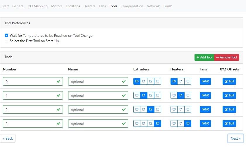
; Z-Probe
M307 H7 A-1 C-1 D-1                                             ; disable heater on PWM channel for BLTouch
M558 P9 H5 F120 T6000                                           ; set Z probe type to bltouch and the dive height + speeds
G31 P25 X0 Y0 Z2.5                                             ; set Z probe trigger value, offset and trigger height
M557 X15:215 Y15:195 S20                                        ; define mesh grid

; Heaters
M305 P2 T100000 B4138 R4700                                     ; set thermistor + ADC parameters for heater 2
M143 H2 S120                                                    ; set temperature limit for heater 2 to 120C
M305 P3 X150                                                    ; configure thermocouple for heater 3
M143 H3 S280                                                    ; set temperature limit for heater 3 to 280C
M305 P4 X151                                                    ; configure thermocouple for heater 4
M143 H4 S280                                                    ; set temperature limit for heater 4 to 280C
M305 P5 X152                                                    ; configure thermocouple for heater 5
M143 H5 S280                                                    ; set temperature limit for heater 5 to 280C
M305 P6 X153                                                    ; configure thermocouple for heater 6
M143 H6 S280                                                    ; set temperature limit for heater 6 to 280C

; Fans
M106 P0 S0 I0 F500 H-1                                          ; set fan 0 value, PWM signal inversion and frequency. Thermostatic control is turned off
M106 P1 S1 I0 F500 H1:2:3:4 T45                                 ; set fan 1 value, PWM signal inversion and frequency. Thermostatic control is turned on

; Tools
M563 P0 D0 H3 F0                                                ; define tool 0
G10 P0 X0 Y0 Z0                                                 ; set tool 0 axis offsets
G10 P0 R0 S0                                                    ; set initial tool 0 active and standby temperatures to 0C
M563 P1 D1 H4 F0                                                ; define tool 1
G10 P1 X0 Y0 Z0                                                 ; set tool 1 axis offsets
G10 P1 R0 S0                                                    ; set initial tool 1 active and standby temperatures to 0C
M563 P2 D2 H5 F0                                                ; define tool 2
G10 P2 X0 Y0 Z0                                                 ; set tool 2 axis offsets
G10 P2 R0 S0                                                    ; set initial tool 2 active and standby temperatures to 0C
M563 P3 D3 H6 F0                                                ; define tool 3
G10 P3 X0 Y0 Z0                                                 ; set tool 3 axis offsets
G10 P3 R0 S0                                                    ; set initial tool 3 active and standby temperatures to 0C
Bed heater temperature is on E1TEMP, output to SSR is on E1 Heater on Duet
Hot end heaters are mapped to E2, E3, E4 and E5 on Duex.
BLTouch servo PWM is on PWM5 on Duex.
You will need to change the M280 command in deployprobe.g and retractprobe.g to use M280 P7.Please check/test this carefully in case I have made any mistakes.
Ian
-
I think it is a configurator bug because creating a new configuration there are problems the heaters created are not displayed in the tools section
-
@droftarts Hi Ian, thanks for your help in solving all these problems. I am sorry that discussions may arise that do not help to reach the goal and are only a cause of waste of time.
I confirm that the Json config I sent was created with the configurator and that the sent config.g corresponds to that generated at the same time by the configurator.
I will follow your advice and install RRF3 so everyone will benefit from it.
I will test with the version of config.g you sent me.
Thanks again for your valuable support
Paolo Francia -
@IngPaoloFrancia you will need to generate a new config.g for RepRapFirmware 3, there are significant differences. The online config tool can generate this. Start by using existing config.json, select firmware 3 on the General tab, and go through each tab. There are more options for assigning heaters etc than with RRF2.
Alternatively, use RRF2 and the config changes from my post above for now.
I am not working today, but others may be able to help you further.
Ian
-
@droftarts Hi Ian I continued to work on finding the right configuration. I used the information you sent me while remaining in RRF2 but the results were not good. I then decided to saturate all the Hw connections of the DUET2 board before engaging those of the DUEX5 and I subsequently set the indices of the heaters, motors and tools accordingly.
I connected the 5 motors for the axis movements to the 5 Duet Driver Chips and I inserted the BLTouch at the end of the PWM chain of heaters on the DUEX5, and the result was excellent.
I send a pdf that shows how the boards have been connected to sensors and actuators and the config.g file generated manually with the correct indexes plus M584 X0 Y1:3 Z2:4 E5:6:7:8 P:3 instruction to Map motors on axis(/assets/uploads/files/1583499901268-final-connection-schematics.pdf) .
I didn't switch to RRF3 because I achieved the goal with the 2.5 release of the FW and because I saw that the command syntax in RRF3 is much more complex and needs further study on my part.
Thanks for the great support you have given me.
regards
Paolo Francia
config.g
Final Connection schematics.pdf