Compiled Firmware with 5bar-Scara / Dual-Arm-Scara
-
I got my old 5-bar arm still on RRF2, struggled a bit with the RRF3 transition.
I'll pull from the git and see what works and what does not work. -
Hi have not used a duet yet but am looking at a scara build and will need additional axis so I’m happy to see this thread and let you know more interested.
Thanks for the work and I look forward to also testing.
-
Hello All.
as the official release, at least the RC-Versions of the firmware now seems to support Dual-Scara.... yeehaa.
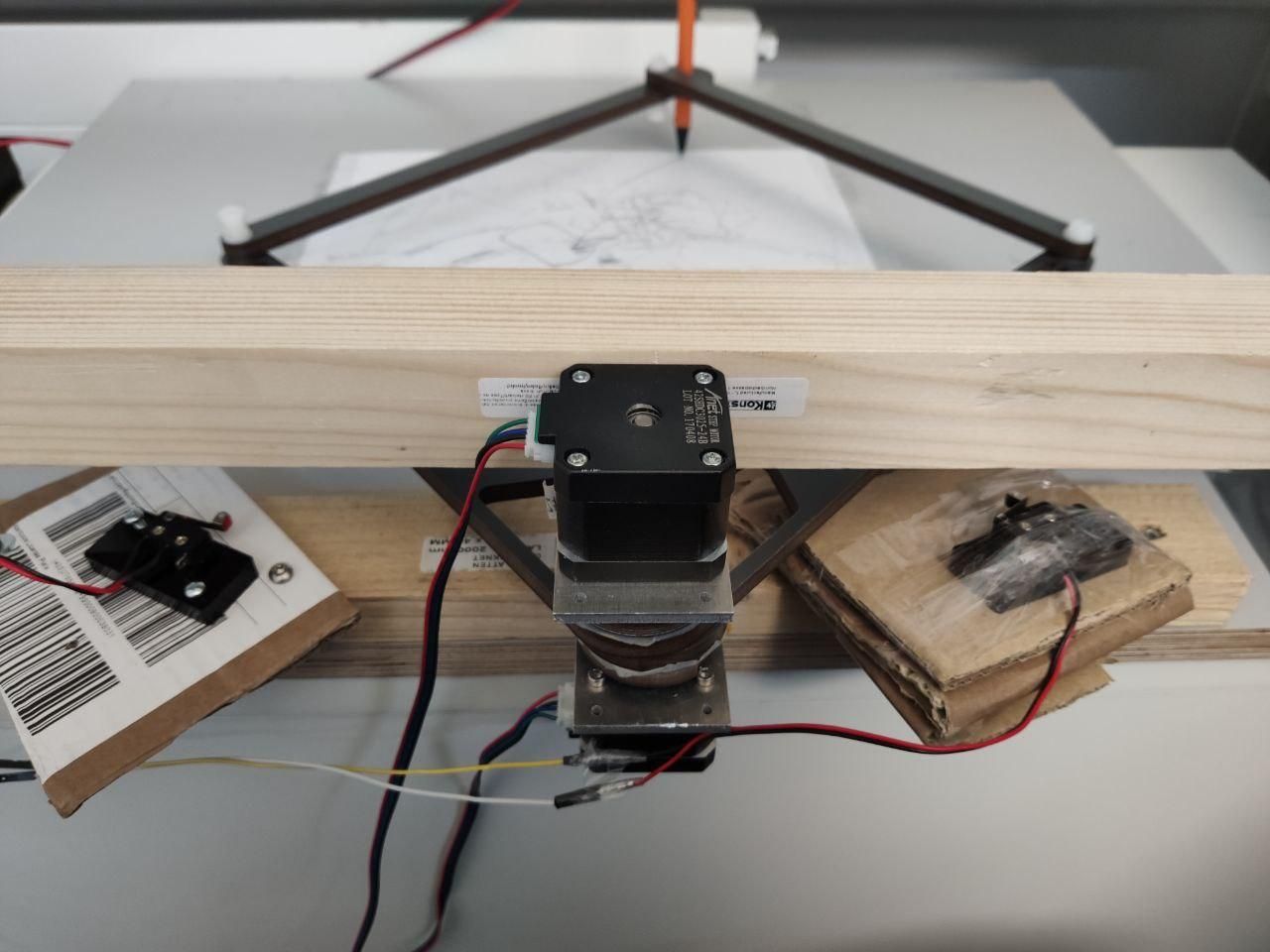
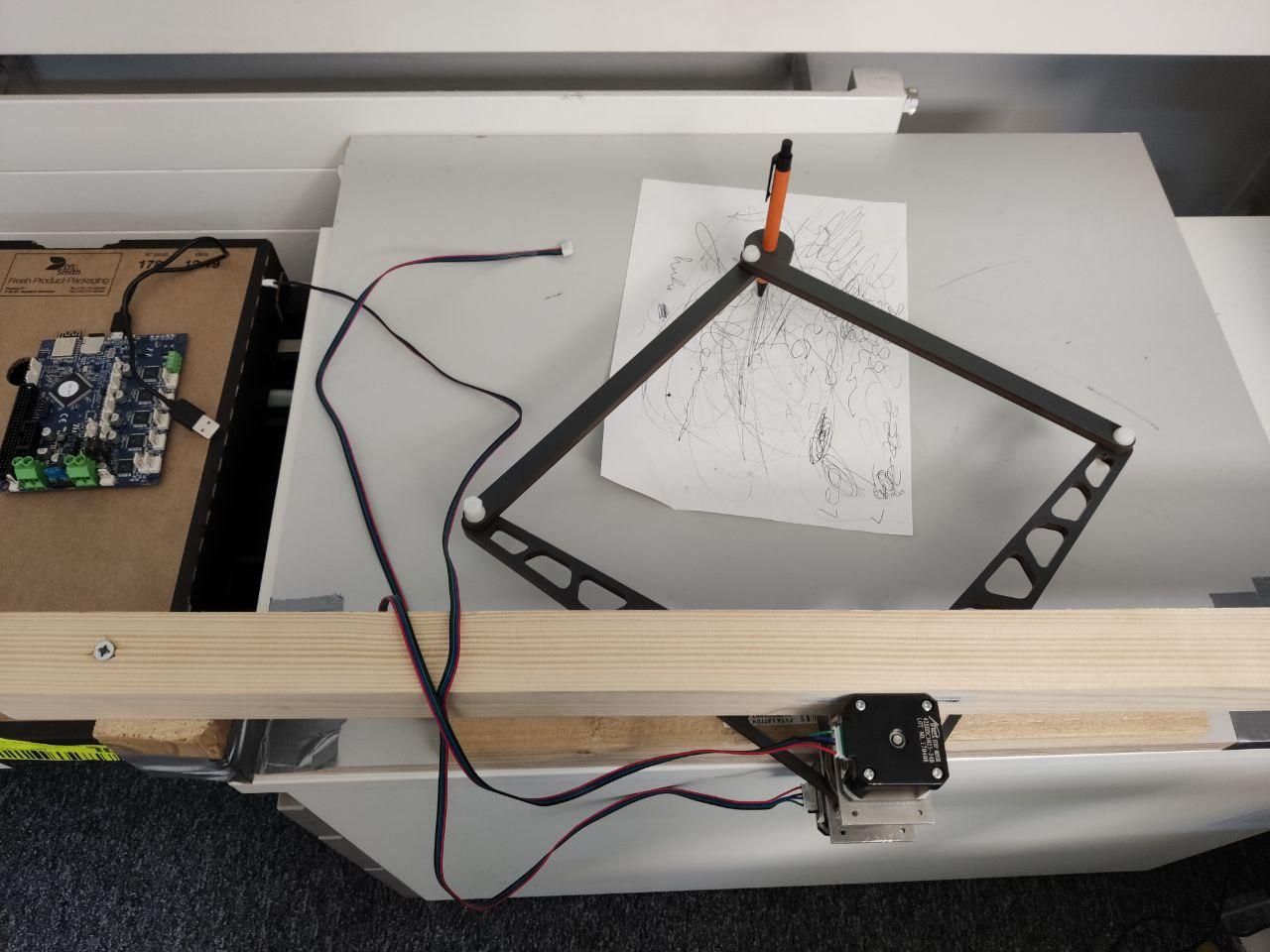
thx to Jörg, Bondus, DC42 and all the other people made this possible !!!Before running in a completely wrong direction i wanted to ask you if there is in your opinion a disadvantage of placing
the steppers like in the Photo. This ways both arms have the same "pivot-point". I am not sure If it is a bad idea because of leverage etc. or the firmware runs into some 0-degree problems....Hopefully i can do my first tries the next days with a new config on the Duet2Wifi.
Best, Johannes
-
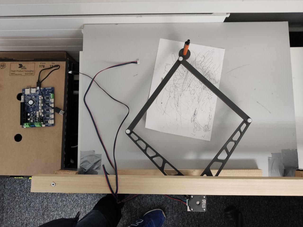
The Printer is doing something
")
G1 S2 X0 Y-30 is doing e.g kind of a quarter-circle. Is this the right behaviour ?
I Changed M669 K11 X0:0 Y0:0 P260:260 D260:260 to M669 K9 X0:0 Y0:0 P260:260 D260:260
as it was showing up Geometry-Type: "Markforged" now it shows "FivebarScara" in Machine PropertiesX0:0 as my steppers are at the same position regarding x/y position, this is right this way ?!
For first testing id like to draw just a small rectangle. What would be the best way to get this done ?
Is it possible to change the Workmode in the config file ? Id like to test Workmode 2
like described here: https://duet3d.dozuki.com/Guide/Five+Bar+Parallel+SCARA/24?lang=enhere is the part of my config-file:
M574 X1 Y1 Z0 S1 ; proximal L and R homing switches trigger when the arm is at
M669 B ; positions and are active high
M669 K9 X0:0 Y0:0 P260:260 D260:260 ; arms are 300 mm long, actuators are 100 mm apart, other parameters take defaults
M350 X128 Y128 Z128 E16 I1 S3 ; Configure microstepping with interpolation
M203 X10000 Y10000 Z300 E3600 ; maximum speeds mm/minute
M92 X100 Y100 Z400 E95.2 ; Set steps per mm
M566 X15 Y15 Z2 E2 ; Set maximum instantaneous speed changes (mm/min)
M201 X50 Y50 Z50 E1000 ; Set accelerations (mm/s^2)
M906 X1000 Y1000 Z700 E600 ; Set motor currents (mA) and motor idle factor in per cent -
@Enpixa Hi Johannes, workmode setting is supported with M669 Ln, e.g. L2 for workmode 2 (described in step 5 of documentation).
I dont't see a disadvantage to set the actuators to the same axis. This special case was descibred in step 15. There are printers using this.
-
Hello Jörg. thx. didnt see that at first sight.
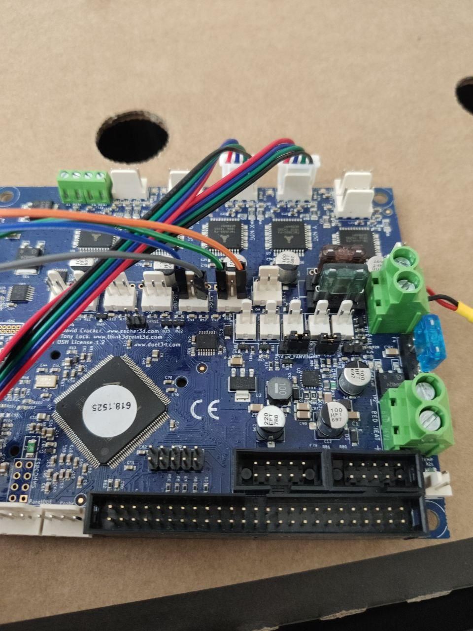
now i installed the endstops. They seem to work hardware-wise. At least the red LEDs next to the Stepper Plug
on the mainboard lighten up when i trigger them by hand. ( i used the endstops from my old Anet A8 and connected them to GND & Stop of X and Y Endstop Pins on Mainboard)Unfortenetly the steppers doesnt stop when triggering the endstop. (Also tried with M574 X1 Y1 Z0 S0 for active low)
Also tried moving +x and -x and pressing the trigger by hand doesnt stop the movement. (LEDs on mainboard show me
a nice red light :)) But the steppers are still moving....... I move the arm with G1 S1 X10 F20 this makes my left-arm (x) moving towards me.M119 gives me Endstops - X: no endstop, Y: no endstop, Z: no endstop, Z probe: at min stop
This is the part of my config.g
M574 X1 Y1 Z0 S1 ; ( Also tried M574 X2 Y2 Z0 S0 )
M669 B60:60; Axis Limits
M208 X-300 Y-300 Z0 S1 ; Set axis minima
M208 X300 Y300 Z300 S0 ; Set axis maximaM669 K9 L2 X0:0 Y0:0 P265:260 D265:260:25:0 ; arms are 300 mm long, actuators are 100 mm apart, other parameters take defaults
Any ideas what i am doing wrong ?
Best, Johannes
-
@Enpixa I expect that a definition of the endstop pins is missing, please check the document https://duet3d.dozuki.com/Wiki/RepRapFirmware_3_overview , e.g. "Endstop numbers are no longer used in M591. Pin names replace them." At the end of this document is an overview of the pin names for the different boards.
If you don't find the reason, please post your complete config file and the type of hardware and firmware (I know it, but the others may not).
-
Jörg, you are crazy being up that late
I am running on a Duet2Wifi 1.04 - with latest Firmware Release 3.01-RC3
Actually im running my X-Arm with : G1 S2 X10 F20 to make it moving towards me.Endstop Pins are connected like shown here:
This is my complete config.g
; General preferences
G90 ; Send absolute coordinates...
M83 ; ...but relative extruder moves
M552 S1 ; Turn network on; Network
M111 S0 ; Debug off
M550 P********* ; Machine name and Netbios name (can be anything you like)-
M551 P********* ; Machine password (used for FTP)M586 P0 S1 ; Enable HTTP
M586 P1 S1 ; Enable FTP
M586 P2 S1 ; Enable Telnet; Drives
M569 P0 S1 ; Drive 0 (X) goes forwards
M569 P1 S1 ; Drive 1 (Y) goes forwards
M569 P2 S1 ; Drive 2 (Z) goes forwards
M569 P3 S1 ; Drive 3 (E0) goes forwardsM574 X2 S1 P"xstop" ; X min active high endstop switch
M574 Y2 S1 P"ystop" ; Y min active high endstop switch
;M574 Z1 S0 P"zstop" ; Z min active high endstop switchM669 B60:60
M669 K9 L2 X0:0 Y0:0 P265:260 D265:260:25:0 ; arms are 300 mm long, actuators are 100 mm apart, other parameters take defaults
M350 X128 Y128 Z128 E16 I1 S3 ; Configure microstepping with interpolationM203 X10000 Y10000 Z300 E3600 ; maximum speeds mm/minute
M92 X100 Y100 Z400 E95.2 ; Set steps per mm
M566 X15 Y15 Z2 E2 ; Set maximum instantaneous speed changes (mm/min)
M201 X20 Y20 Z20 E1000 ; Set accelerations (mm/s^2)
M906 X1200 Y1200 Z700 E600 ; Set motor currents (mA) and motor idle factor in per centM84 S0 ; Set idle timeout
; Axis Limits
M208 X-300 Y-300 Z0 S1 ; Set axis minima
M208 X300 Y300 Z300 S0 ; Set axis maximaIf anyone has an idea... this would be really great !
Thanks alot, Johannes -
@Enpixa I am not an endstop expert, but I think it is necessary to define and use a Z endstop even you don't need it. But I'm not sure.
-
@JoergS5 said in Compiled Firmware with 5bar-Scara / Dual-Arm-Scara:
@Enpixa I am not an endstop expert, but I think it is necessary to define and use a Z endstop even you don't need it. But I'm not sure.
No, it's not necessary with RepRapFirmware.
-
@Enpixa said in Compiled Firmware with 5bar-Scara / Dual-Arm-Scara:
M574 X1 Y1 Z0 S1 ; ( Also tried M574 X2 Y2 Z0 S0 )
As you are running RepRapFirmware 3, you need to specify the endstop pin names. If the endstop LEDs are normally on but go out when the endstop is triggered (which is the case when using normally closed switches, recommended) then you need:
M574 X1 S1 P"xstop"
M574 Y1 S1 P"ystop" -
Hello DC42,
thats what i already did, see my latest post/config: https://forum.duet3d.com/topic/13631/compiled-firmware-with-5bar-scara-dual-arm-scara/18
@Enpixa said in Compiled Firmware with 5bar-Scara / Dual-Arm-Scara:
M574 X2 S1 P"xstop" ; X min active high endstop switch
M574 Y2 S1 P"ystop" ; Y min active high endstop switch
;M574 Z1 S0 P"zstop" ; Z min active high endstop switchI tried all thinkable variations ( active low/high / trigger min/max )
Right now, i dont know what more i could try to make it work.
-
@Enpixa I don't have more ideas. I would try a last test inverting with the ! sign *), then trying other endstop hardware.
*)
P"pin_name" Defines the pin name(s) that the endstop(s) for the specified axis are connected to. Needed when S=1. May need ! before pin name to invert signal. in https://duet3d.dozuki.com/Wiki/Gcode#Section_M574_RepRapFirmware_Num_3 -
Is the red LED on the mainboard a good indicator if it is working properly hardware-wise ? Because when
i press the endstop manually the LED is on. if not pressed it is off.If you have a recommendation for me which endstops i should buy. i would appreciate it.
-
@Enpixa i've read "The second line (S1) defines all
active high endstops.
If you are unsure if your endstops
are active high or active low, you
can test them by observing the
light next to the corresponding
stepper motor connector. If the
light is lit when the button is
pressed, then this would indicate
an active low endstop"
in https://dozuki-guide-pdfs.s3.amazonaws.com/pdf/duet3d/guide_10_en.pdf page 11. So the light tells you the type of endstop. If it is the light you mean, then it would be a active low endstop. -
@Enpixa which type of endstop recommendation: for your current printer setup the endstop would be sufficient imho which you use. An alternative would be an optical endstop.
I want to go another direction with an optical encoder like described in https://github.com/JoergS5/OpticalEncoder
-
Hello Jörg,
thx for that information, for my understanding i got an active low endstop. LED next to stepper plug is lit when endstop is pressed.
Video of pressing Endstop: http://nörds.de/video_2020-03-05_14-04-43_1.mp4
This is the direction setting used in my Config
M569 P0 S1 ; Drive 0 (X) goes forwards
M569 P1 S1 ; Drive 1 (Y) goes forwards
M569 P2 S1 ; Drive 2 (Z) goes forwards
M569 P3 S1 ; Drive 3 (E0) goes forwardsThat Information i found for setting the endstops
The electrical type of the endstop (S parameter). This used to be just active high (S1, e.g. a normally-closed switch or opto switch), or active low (S0, e.g. normally-open switch or Hall sensor). There are now also options for using a Z probe (S2) and for using motor stall detection (S3).
These are the X, Y and Z parameters. 0 means no endstop present, 1 means an endstop switch at the minimum end, 2 means an endstop switch at the maximum end of the axis.
As the Arm is moving towards me and the Endstop when using positive X-Values i set X and Y to 2 for maximum checking. (G1 S2 X20 F100 makes the arm moving in direction to the endstop)
M574 X2 S0 P"xstop" ; X max active low endstop switch
M574 Y2 S0 P"ystop" ; Y max active low endstop switch
;M574 Z1 S0 P"zstop" ; Z min active high endstop switchI just set an Axis-Limit
; Axis Limits
M208 X-300 Y-300 Z0 S1 ; Set axis minima
M208 X300 Y300 Z300 S0 ; Set axis maximaBest, Johannes
-
Cool! Another 5-bar.
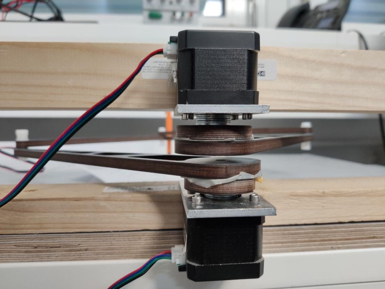
By putting the proximal inner joints on top of each other you actually have a 4-bar, the 5'th has zero length. I hope the math in the code works, it is a special case.
One effect of that is that most of the work modes no longer work, you will always be in work mode 2. Assuming your proximal arms have the same length.Your case with all arms the same length and inner joints in the same place is actually a much simpler case than what the current implementation can handle, but it should work fine.
I think your homing move is not right, you should use the H1 option to G1.
My homing file "home5barscara.g":
G91              ; relative positioning

G1 H1 Z300 F1500 ; move quickly to endstop and stop there (first pass)
G1 H2 Z-5 F900      ; go back a few mm
G1 H1  Z300 F90  ; move slowly to endstop once more (second pass)

G1 H1 X300 Y300  F2500 ; move quickly to endstop and stop there (first pass)
G1 H1 X300 F2500
G1 H1 Y300 F2500
G1 H2 X-2 Y-2 F900      ; go back a few degrees
G1 H1 X300 F90  ; move slowly to endstop once more (second pass)
G1 H1 Y300 F90  ; move slowly to endstop once more (second pass)

G0 Z-2  ; move down a bit to not make mesh calibration move it out of machine limits
G90              ; absolute positioning

G0 X0 Y0 F6000 ; move to a reasonable position
You would have to remove z-homing and make X (or is it Y?) move towards negative instead. I have my right arm homing switch in between the arm joints.
I think your steps/mm, G92, is wrong. It should be steps/deg in this case.
Assuming you have 200step/rev steppers. it should be 71.1111111111.
200 steps/rev * 128microstepping / 360degrees = 71.1111....
With the steppers directly attached to the arms you should be able to move stupendously fast but with pretty poor precision. -
@Enpixa said in Compiled Firmware with 5bar-Scara / Dual-Arm-Scara:
Is the red LED on the mainboard a good indicator if it is working properly hardware-wise ? Because when
i press the endstop manually the LED is on. if not pressed it is off.That's as expected for a normally-open switch; however normally-closed switches are preferred (which reverses the sense). The LED is a reliable indicator when the endstop is a simple microswitch. It isn't always reliable if the endstop is an optical switch.
-
Hi Bondus, thx for your feedback. Yes, in future i will use some kind of gears. For the very first protoype
i wanted the Software/Firmware getting working... later on alle the fine-tuning, rigid mechanics etc.********* UPDATE **********
I found this important info in the doku.Endstop type S0 (active low switch) is no longer supported in M574 commands. Instead, use type S1 and invert the input by prefixing the pin name with '!'. Ex: M574 X1 S1 P"!xstop" I think Jörg also mentioned it somewhere before.
Now is see pressing the X-Endstop with M119 !
Endstops - X: at max stop, Y: not stopped, Z: not stopped, Z probe: at min stop
Yeeehaa ! Thx alot, Video of first time homing:
http://nörds.de/first_time_homing.mp4
Best, Johannes