PWM to DC for fan control for cheap - How to do it.
-
I like it!
It has broad application beyond just Duet.
Is this something you'd want to document at RepRap.org, and let anyone produce "batches" of them?
Delta / Kossel printer fanatic
-
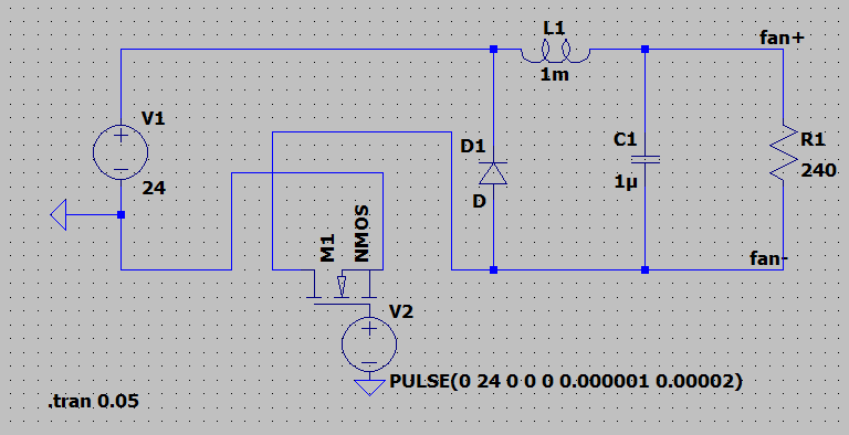
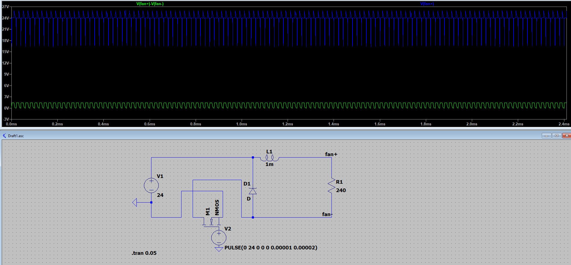
You haven't shown where you measured the output voltage of the simulation that you posted. It certainly isn't the voltage across the 240 ohm resistor that represents your fan. Also you have an odd 100M resistor in the circuit, and it's not clear whether you have grounded the negative side of the 24V supply.
Duet WiFi hardware designer and firmware engineer
Please do not ask me for Duet support via PM or email, use the forum
http://www.escher3d.com, https://miscsolutions.wordpress.com -
I like the idea. Using a pull up resistor to handle output pulling to the ground is a good idea. What is not that ideal is that you need to get 3 wires to the board (Vdd, Vss, Fan#-) but I don't see a way around it. What is IMO a huge problem is that there is zero protection. I don't see any in the original duet circuit too :(, I'd expect a 10-20R between FAN0- and TR5 or between TR5 and GND
So you might want to add R in series with the FAN so if a short happens on the fan leads (and it is more common than one would expect, I replaced 30+ fets driving fan's on different 3d printer boards for different ppl) your opamp doesn't blow up. Also, you really want a diode parallel to that FAN (like on original Duet schematic)
-
@Danal Yes, I would definitely like to see them made and sold to the general public. I will make a post about it there whenever I will get some free time.
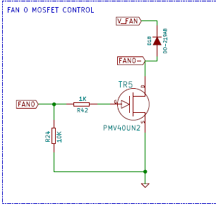
@dc42 My bad, I guess I should have made the diagrams slightly clearer.
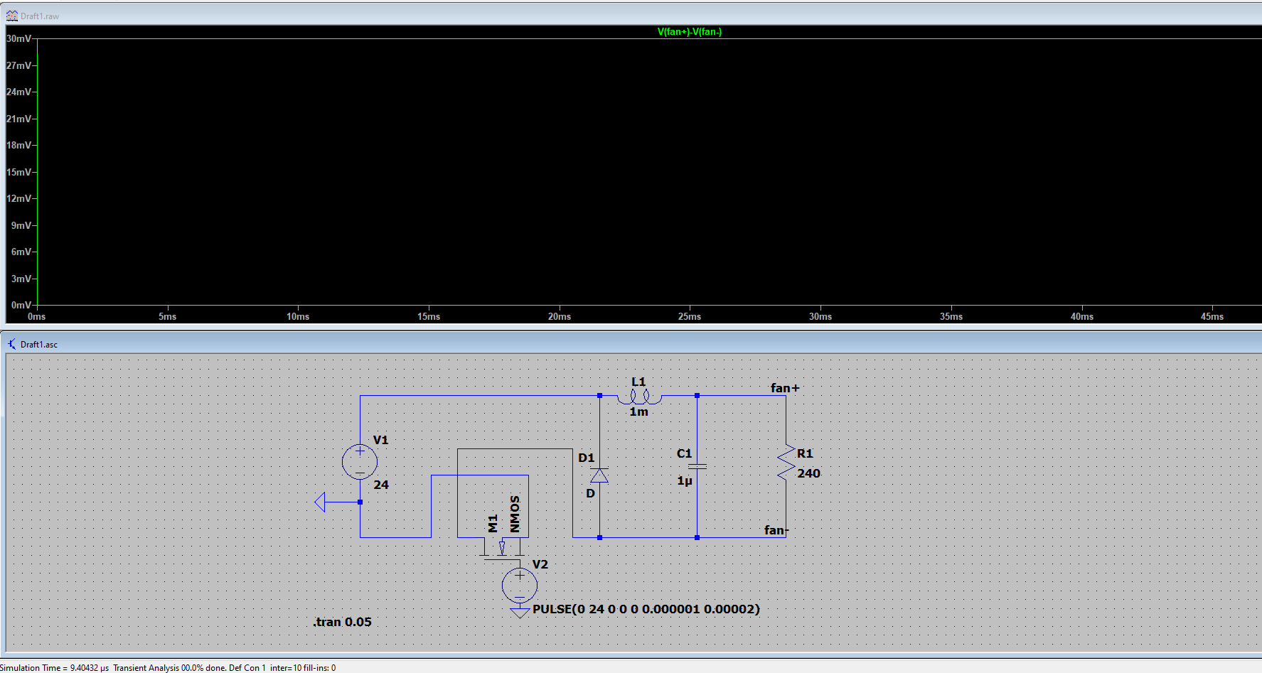
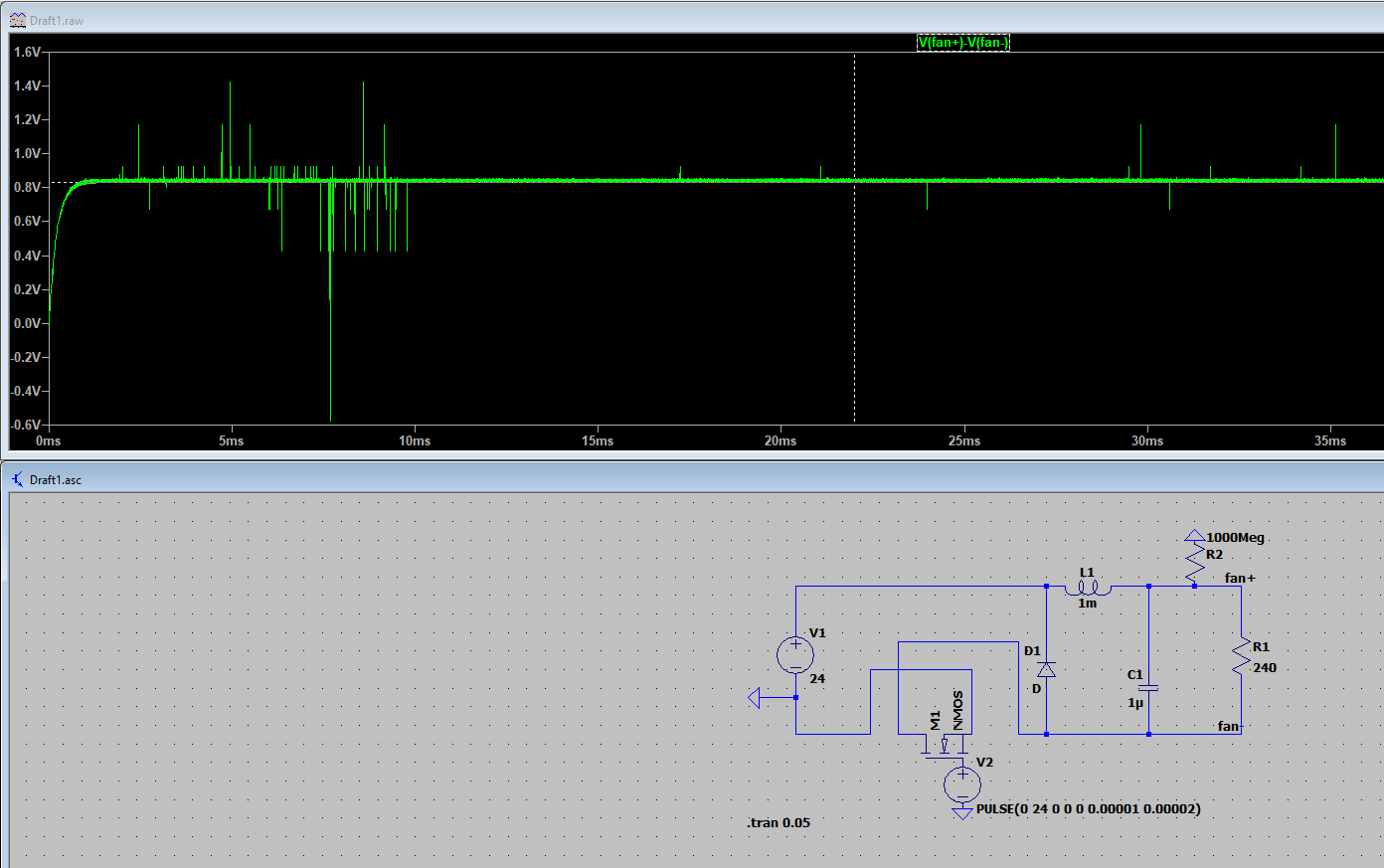
The 100M resistor is there because LTspice throws a "Singular matrix" error without it, since it thinks that there is a node floating. Adding the 100M resistor is a quick solution that does not affect the circuit given how large it is. I haven't saved it, and now I tried to redraw it, but for some reason I get the same error even with the 100M resistor. If I add a large resistor to every node the error goes away, but it only simulates up to a few microseconds, and then LTspice freezes.
The negative terminal of the 24 supply was grounded, there is a small blue triangle there which indicates ground.
I guess it is possible that I made an error in the simulation of the LC circuit as I am not able to run it again. I will try again later.
@arhi The additional resistor would reduce the max voltage of the fan. Wouldn't it be a good idea to add instead a resettable fast blow fuse?
Also I thought the flyback diode is only really needed for normal brushed fans, and not for brushless ones. Since the whole point of this module is to make brushless fans work better with pwm (brushed DC ones, if they exist in these sizes, would already handle PWM quite well), would a flyback diode still be needed? -
@dc42 !
Okay so I tried recreating the LC circuit again on a fresh install of LT spice on a different PC. It did allow me to start simulation without the 100M resistor. Here is the new diagram:
However when trying to simulate it, it freezes after less than 10 microseconds
I tried removing the capacitor, giving this result:
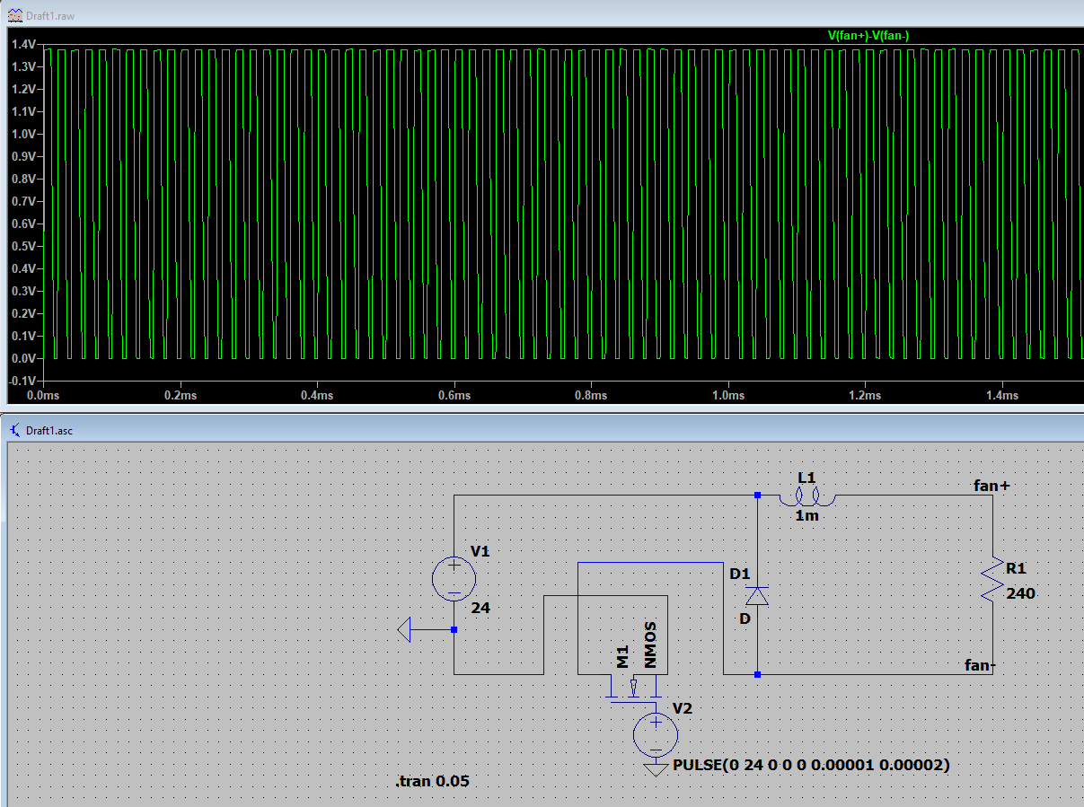
Turns out the waveform I measured the 26V spikes on was from the fan positive to actual ground, not the negative fan terminal, so you were right. My original statement saying that it is dangerous is wrong. However, the circuit is not working as expected (at least without the capacitor, no idea why it does not run with it), as if I change the PWM ratio, the average voltage stays the same.
Edit: Managed to get it running with the capacitor. The extra 1GOhm does not affect the measurements, but the simulation does not run without it. Here are the results:
-
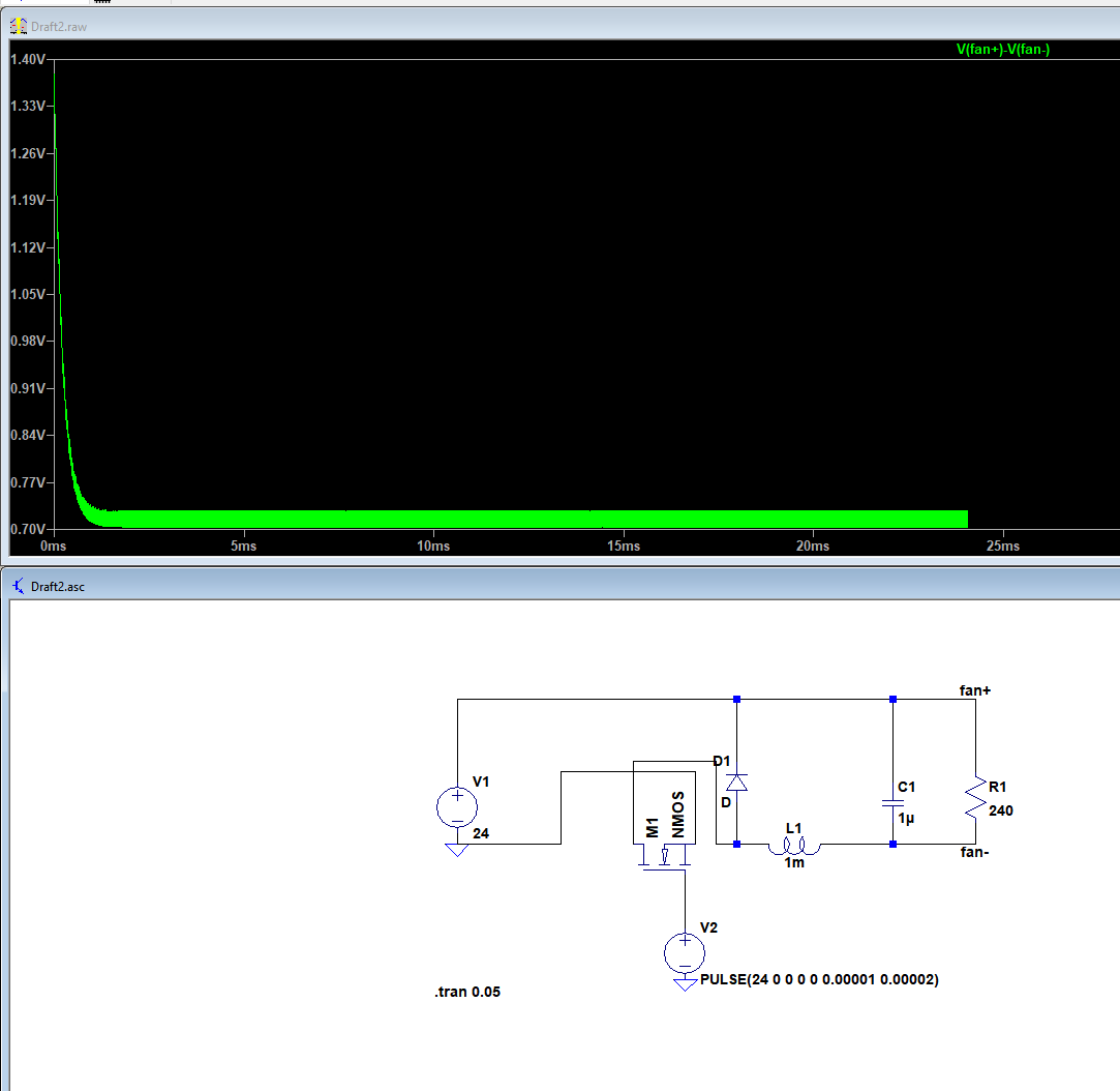
Try connecting the inductor between the bottom ends of the diode and capacitor instead of the top ends. The simulation program might be happier with that.
Duet WiFi hardware designer and firmware engineer
Please do not ask me for Duet support via PM or email, use the forum
http://www.escher3d.com, https://miscsolutions.wordpress.com -
@dc42 That has indeed fixed the simulation errors for the LC filter. However the voltage across the resistor (fan) is still less than about 1V, no matter the PWM ratio.
-
I recently ran into this same issue and was surprised no one made a easy plug and play solution. I ended making an simple RC circuit since thats what I had on hand at the time. But it would be great to be able to get this as an add-on
-
@vfjr said in PWM to DC for fan control for cheap - How to do it.:
@arhi The additional resistor would reduce the max voltage of the fan. Wouldn't it be a good idea to add instead a resettable fast blow fuse?
yes, something like this would be better then a simple res
Also I thought the flyback diode is only really needed for normal brushed fans
yes, but you never know what will someone use on the other side and for few cents better safe then sorry
-
@vfjr said in PWM to DC for fan control for cheap - How to do it.:
@dc42 That has indeed fixed the simulation errors for the LC filter. However the voltage across the resistor (fan) is still less than about 1V, no matter the PWM ratio.
In that case there is something wrong with your simulation. Maybe the mark/space ratio isn't what you think. Where are you measuring the output? What does "PULSE(24 0 0 0 0 0.00001 0.00001)" signify? And ".tran(0.05)"? Did you have to specify a value for the series resistance of the inductor?
-
Hello! Can you please post what is m1 mmos and what pins used ? or post close photo module of both sides, need to fix fan whine on my ender 3, thanks alot!