PWM Fan Control Issue using 24V to 12V Regulators
-
Hello,
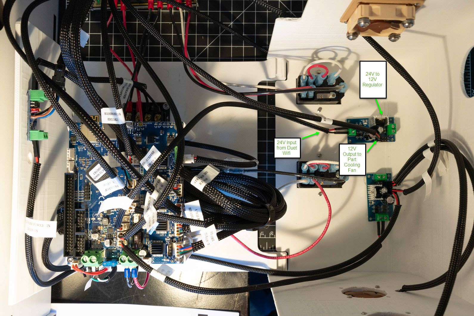
I am having strange issues with my current setup. Long story short, I have been using these 24V to 12V regulators (Link) for my case fans, and the hotend/part cooling fan for a few weeks on a brand new Duet 2 Wifi. This has been working for that length of time with no changes to the config.g or any hardware/wiring changes.
As of a few days ago, however, the part cooling fan is no longer responding via PWM Fan 0 port on the board. The fan is still receiving 12V evenly with the regulator. I then tried moving the connector from the Fan 0 slot to Fan 1 and it worked without modifying the config.g file for a second up until I changed the speed in Duet Web Control from 0 to 100%. The fan went to 100% but now cannot be turned off. So at this point PWM Fan 0 and 1 are responding the same way. I chose not to connect the 24V to 12V regulator to the Fan 2 spot just to be sure, and decided to connect the 12V part cooling fan directly to Fan 2 on the board and it does work as expected, at 24V. I just did this for test to see if I had control, but can't sustain that setup with the 12V blower fan.
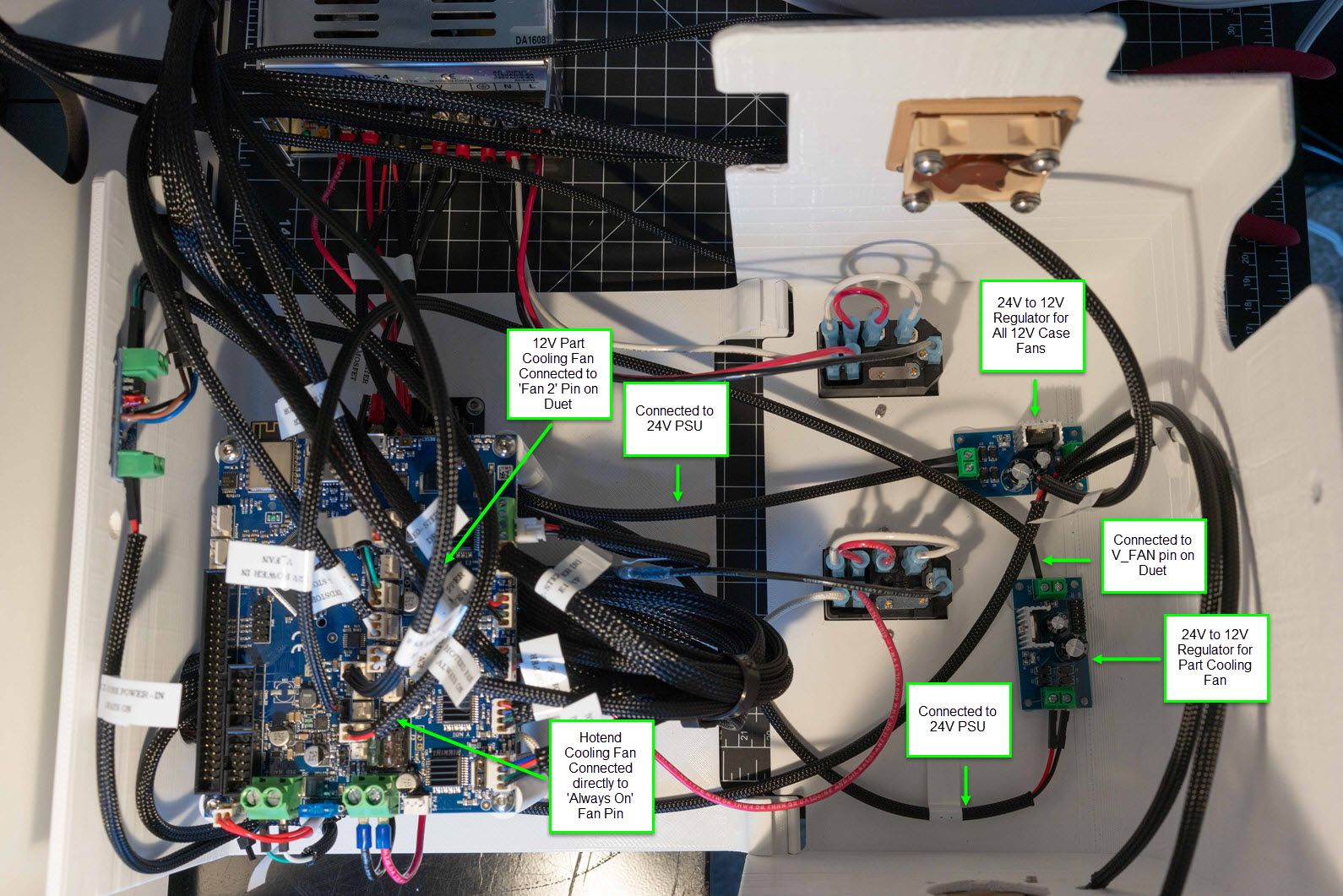
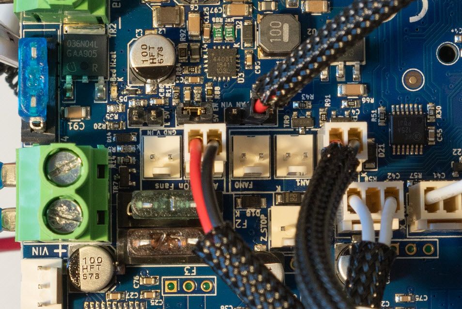
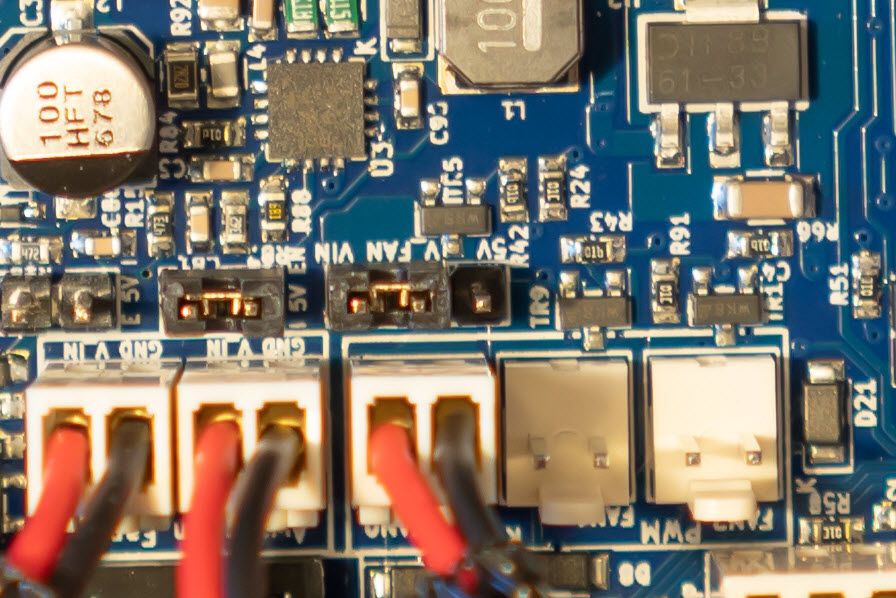
I have researched others with PWM fan issues on this forum but can't seem to find answers similar enough to my issue. I have attached images of the MOSFETS on the board and another of the setup with the regulators. I have tried sending the M106 commands on the Fan 0 and Fan 1 after the issues started and have had no luck with turning the fans off. Fan 2 remains fine, but I do not want to connect the regulators to this Fan 2 slot in-case I lose all 3 PWM fan pins on the board. I understand the wiring might not be correct for the regulators to handle quick voltage changes for PWM, but this is why I'm at a lost for answers since this setup worked for weeks before.
I am not sure if damage was done to the board since it doesn't seem the MOSFETS are blown, so looking for any help on this issue.
Thank you!
-
It looks like you have the negative leg connected through the regulator as well? This would likely cause issues with PWM. You can bypass the regulator on the negative leg and have the fan directly going to the negative pin on the board. Since the Duet switches PWM on the negative side you should have proper control of your fans.
Or, if all your fans are 12v, it would make more sense to use the regulator to provide 12v power directly to the V_fan pin (rather than jumpering it with VIN), which would provide all the fans with 12v directly.
As shown here: https://duet3d.dozuki.com/Guide/Ender+3+Pro+and+Duet+Maestro+Guide+Part+5:+Upgrades/54#s214
-
Thank you for that advice! I will try that and get back to you.
I'm assuming the board isn't at fault as a result of the current wiring setup?
-
I have changed the setup and moved the regulator output (+) to the V-Fan pin on the Duet and everything is working as it should for my 12V part cooling fan.
Only issue is, I still don't seem to have control on the Fan 0 and Fan 1 ports anymore and don't understand why since it does not look like anything was short circuited/blown out? These will still only operate at 100%. Maybe I am missing something simple?
Anyway, thank you for the quick help! This will at least allow me to continue printing.
-
I think your I parameter in M106 command is not what you want. I-1 means - fan is disabled. If you want to invert PWM signal, then it should be I1, or for normal operation I0.
-
@aidar The code I posted was what I normally used when I was on Fan 0 slot when everything was working. When I tested the other slots, I made sure to enable the fans with I0 and changed the corresponding P value to the fan slot. The only one that seems to work correctly now is Fan 2 for some reason. Not sure if the regulator messed something up on the board during my original setup. Its just odd that it worked before without any changes to code or wiring and now it has caused PWM Fan 0/1 to only provide 100% voltage.
-
hmm...didnt see that at first, but on your picture seems that there are nothing connected to PWM fan1 and fan2 connectors. And your 2 fans are connected to "always on" connectors.
-
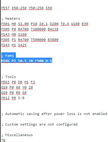
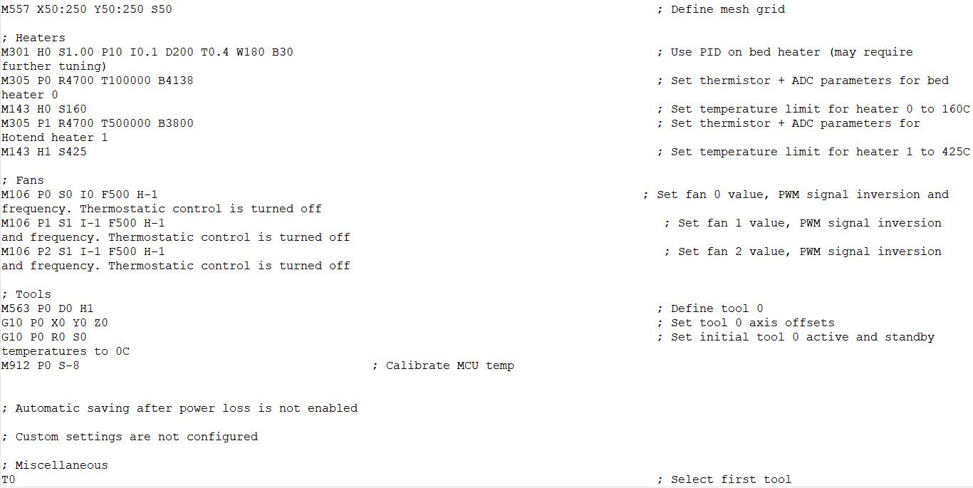
Some of my always on fans used to be connected to the Fan 0 and 1 slots but I am using one of the regulators to control all of them off one 'Always on' port on the board. I can really just delete the other M106 code out since I only use on of the slots for the part cooling fan. Currently, I have a 12V regulator with the part cooling fan on Fan 2 so the code is M106 P2 S0.5 I0 F500 H-1. This works now, but I still can't get the Fans 0 and 1 to respond to PWM anymore.
-
Some fans don't play well with the default PWM frequency. You can experiment with adjusting the frequency with M106 F value. Values from 10 to 30000 are valid.
Can you update us with your current config and wiring, just for clarity?
-
I tried changing the frequencies as well without success. But I have been using the same blower fans and have been successful with 500Hz.
I'm away at the moment, but will post pics as soon as I get back.
-
-
Well saw this on another forum Post:
https://forum.duet3d.com/topic/7518/fans-on-different-voltages
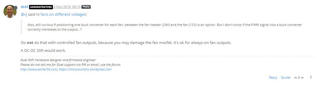
I assume the Mosfets on the board are damaged due to my initial wiring setup using the 24-12V regulator directly on the 24V PWM Fan 0 & 1 pins instead on converting the row to 12V via the V_FAN pin. They do not look blown from the pics, but something isn't functioning correctly anymore.
Hopefully this helps anyone else that may have made this mistake.