Toolboard Extruder Motor Stutters (most of the time)
-
@wesc said in Toolboard Extruder Motor Stutters (most of the time):
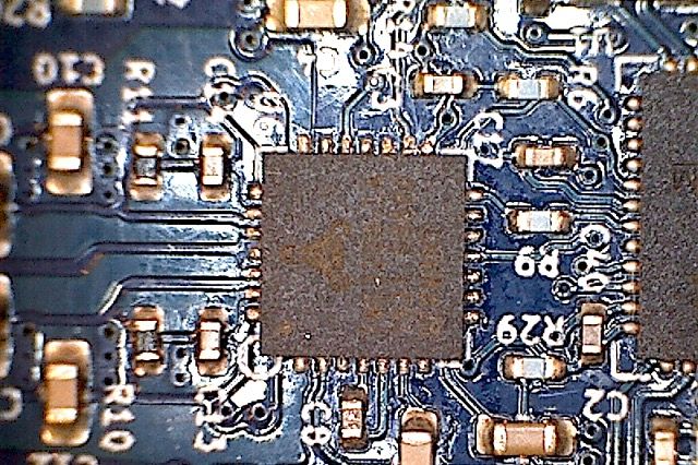
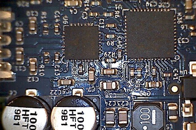
I think the driver is bad or bad toolboard connection . The solder on the tmc2209 pins is less than perfect. There might be an unintentional solder bridge between 2 of the pins on the atmel chip. Hard to tell.
Can you post a good photo? IIRC, TMC chips have some dual pins to a common pad for total current carrying ability; these often look like solder bridges, but are actually OK.
-
Hi @wesc, your M122 report is reporting short-to-ground, which explains the lack of proper movement. Please verify with a multimeter (and power off) that you still have:
- 2 ohms between pins 1 and 2 of the motor output (measured on the underside of the tool board)
- 2 ohms between pins 3 and 4
- No continuity between any other pair of pins (e.g. 1 and 3)
- No continuity between any of those pins and the frame of the motor
If the board is mounted on the Hemera, also make sure there is no possibility that any part of the back of the tool board is shorting against the Hemera frame.
-
1-2: 2.2 ohms
3-4: 2.2 ohms
All other pairs are 2.5 megaohms or more
Board was on Hemera, but i used extra standoffs in addition to the plastic ones and clipped the protruding part leads to shorten them. Happens with the board off the Hemera as well.Attached pics from the world's finest $15 USB microscope. Solder on the leads looks a little blobby.
-
@wesc The M584 command for your extruder needs to come BEFORE the motor settings. Currently you have:
; Drives M569 P0 S1 ; physical drive 0 goes forwards M569 P1 S1 ; physical drive 1 goes forwards M569 P2 S0 ; physical drive 2 goes backwards M569 P3 S0 ; physical drive 3 goes backwards M569 P4 S0 ; physical drive 3 goes backwards M569 P5 S0 ; physical drive 3 goes forwards M569 P20.0 S0 M584 X0.5 Y0.1 Z0.2:0.3:0.4 ; set drive mapping. 0.0 reports short to ground M350 X16 Y16 Z16 E16 I1 ; configure microstepping with interpolation M92 X160.00 Y160.00 Z1600.00 E409.00 ; set steps per mm M566 X900.00 Y900.00 Z12.00 E120.00 ; set maximum instantaneous speed changes (mm/min) M203 X18000.00 Y18000.00 Z1000.00 E1200.00 ; set maximum speeds (mm/min) M201 X3500.00 Y3500.00 Z420.00 E250.00 ; set accelerations (mm/s^2) M906 X2500 Y2500 Z1500 E800 I30 ; set motor currents (mA) and motor idle factor in per cent M84 S30 ; Set idle timeout ; Axis Limits ... ; Endstops ... ; Z-Probe ... ;Z config ... ; Temperature Sensors ... ; Heaters ... ; Fans ... ; Hemera - Reconfigured via M952 B121 A20 to be at address 20 ; Hemera motors M569 P20.0 S0 ; set tool extruder direction M584 E20.0 ; set extruder drives ; Hemera sensors and heaters etc Move the Hemera section up to below the M584 that defines the other axes (ie under line number 10 above), otherwise it's using the default motor settings. Remove one of the M569 P20.0 S0 commands.
Ian
-
Ugggh, so this is weird. I updated the firmware thinking it could have been a firmware issue (long shot, I know).
M997 B20
After waiting many miinutes with no response, I power cycled.
'
Now the Duet3 isn't communicating with my Toolboard - tons of CAN response timeouts. No slow red flash, just the solid blue and solid red leds. The heater and fan turned on (I see the warning about that in the docs), so i removed all connections to the board except CAN and power and stepper.I tried a double button power on to reset.
M115 B121 (or 10 or 20, the address i previously programmed) also error.
M409 K"boards" yields this:{"key":"boards","flags":"","result":[{"canAddress":0,"firmwareDate":"2020-03-16b1","firmwareFileName":"Duet3Firmware_MB6HC.bin","firmwareName":"RepRapFirmware for Duet 3 MB6HC","firmwareVersion":"3.01-RC4","iapFileNameSBC":"Duet3_SBCiap_MB6HC.bin","iapFileNameSD":"Duet3_SDiap_MB6HC.bin","mcuTemp":{"current":29.4,"max":29.5,"min":18.3},"name":"Duet 3 MB6HC","shortName":"MB6HC","supports12864":false,"v12":{"current":12.2,"max":12.3,"min":12.2},"vIn":{"current":23.9,"max":24.0,"min":23.9}}]}
Seems the bootloader got corrupted.
Is there a bossa solution to reprogram the bootloader on a Toolboard?
-
Ian has identified the root cause of the original problem: your M906 command that sets the extruder current was earlier in config.g than the M584 command that defined the extruder driver. So the motor current wasn't being set, which would result in less than 100mA current.
I'm not sure why the firmware update failed. Did you notice any flashing of the red LED during the update process? If the firmware file you tried to install did not have a valid CRC then it would have repeatedly tried to fetch and install the firmware, and the LED would flash at intervals. If you turned the power off while it was writing to flash memory, perhaps that corrupted the bootloader (it's not clear from the datasheet whether the bootloader protection provides adequate protection if power is removed while another part of the flash memory is being written).
What I would like you to do now is to disconnect the CAN connector from the tool board, and once again power the board up while both buttons are held down (then release them after powering up). If the red LED between the two buttons show no activity at all, I will authorize a warranty replacement, because re-installing the bootloader requires an Atmel ICE or similar SWD programming tool. If you do get any activity from that LED, please report what flashes you see.
-
@dc42 said in Toolboard Extruder Motor Stutters (most of the time):
an has identified the root cause of the original problem: your M906 command that sets the extruder current was earlier in config.g than the M584 command that defined the extruder driver. So the motor current wasn't being set, which would result in less than 100mA current.
In original post: "Increasing current to 1500 with M906 just makes it louder.", so Ian's theory isn't correct. (wasn't totally obvious that I did that with the console)
-
@dc42 said in Toolboard Extruder Motor Stutters (most of the time):
ly tried to fetch and install the firmware, and the LED would flash at intervals. If you turned the power off while it was writing to flash memory, perhaps that corrupted the bootloader (it's not clear from the datasheet whether the bootloader protection provides adequate protection if power is removed while another part of the flash memory is being written).
What I would like you to do now is to disconnect the CAN connector from the tool board, and once again power the board up while both buttons are held down (then release them after powering up). If theThe .bin file was the same one I originally flashed to the Toolboard that was uploaded to /sys
Just tried a reboot with CAN disconnected and buttons pressed. No LEDs on between the buttons, and no bootloader/CAN connection.
-
@wesc It's not just the current, it's all the motor settings. From M584:
Order dependence
M584 must come earlier in config.g than any M350 and M906 commands. If it creates new axes, it must also be earlier than any M92, M201, M203, M208, M350, M566, M574, M667 and M669 commands.Ian
-
Ah. Wish i could try the different order.

-
I authorise a warranty replacement for your tool board.